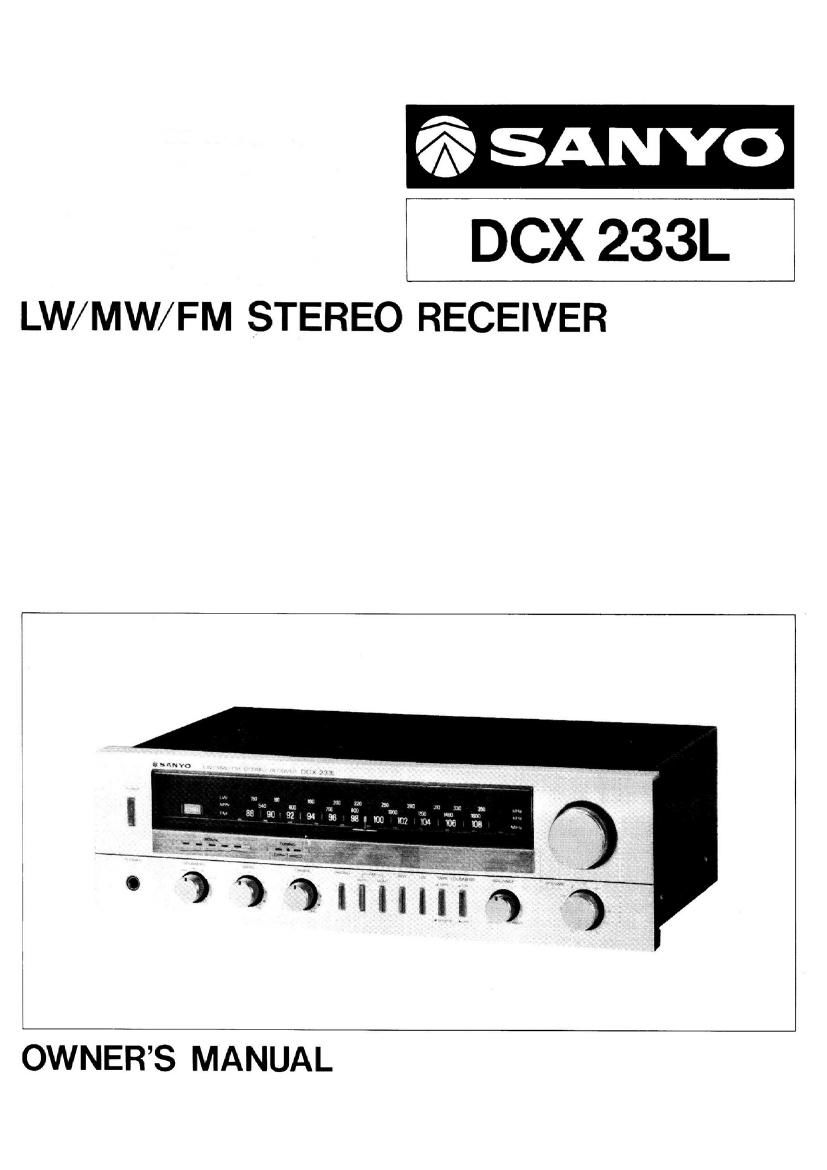
Sanyo DCX 233L Owners Manual

This is the 9 pages manual for Sanyo DCX 233L Owners Manual.
Read or download the pdf for free. If you want to contribute, please mail your pdfs to info@audioservicemanuals.com.

Page: 1 / 9
left right
Sanyo DCX 233L Owners Manual

Extracted text from Sanyo DCX 233L Owners Manual (Ocr-read)


Page 2

ENGLISH

INTRODUCTION

This LW/MW/FM STEREO RECEIVER was developed and
engineered by Sanyo to be a source of entertainment and
listening pleasure for many years to come.

Before you install and start operating your unit, please read
the instructions in this booklet carefully. This will prevent
errors in operation and also help to assure faultless perfor-
mance of your unit and maximum listening enjoyment.

PREPARATION

1. Unpack the unit. (Save carton and fillers for future use.)

2. Make all connections before inserting line cord into an AC
wall outlet.

3. This model has been set previously to the power line for
220 V, however it is switchable to 110 V by the switch
on the rear panel.

CONNECTIONS TO REAR TERMINALS

l. ANTENNA terminals
(1) Communal antenna system

This unit is equipped with 3 DIN coaxial-type socket

and the socket is used for an FM and AM (MW/LW)

antenna of communal receiving system.

When a communal antenna system is available we

recommend that the unit is used exclusively on this

system. This type of operation has the advantage that
both reception bands (FM and AM) are automatically
connected to the unit and no losses occur due to inter-
vening connectors. The connection should be made on

the 75 Q coaxial socket (Fig. 2).

Connecting FM antenna

Choose an appropriate FM antenna, taking the strength

of signals to be received and the prevailing conditions

for FM reception into due consideration.

(See page 6)

O Dipole antenna
Connect the dipole antenna supplied to the antenna
terminals marked FM-300 9 (Fig. 1) or. . .

0 Outdoor antenna with 300 Q feeder-line (Fig. 1)
Connect the lead-in to the antenna terminals marked
FM-300 Q the same way as the dipole antenna or. . .

0 Outdoor antenna with 75 S2 coaxial cable
To minimize noise interference from engines of motor
vehicles and high-tension power lines, the use of a
75 9 coaxial cable is recommended. Connect it to the
FM-75 (2 terminal as in Fig. 2.

NOTE:

In weak signal areas, the use of an FM outdoor antenna and

75 fl coaxial cable is necessary for good FM reception.

Contact a Sanyo dealer for advice.

(2)

(3) Outdoor single-wire antenna for AM (MW/LW) recep-
tion

For the reception of faint AM (MW/LW) signals in
remote areas or inside a steel-concrete building, the
installation of an outdoor single-wire AM (MW/LW)
antenna is recommended.

Spread an insulated wire about 10 m in length as
illustrated (Fig. 3). An antenna of this kind will pick
up radio waves too faint for the ferrite bar antenna
to receive.

A single-wire antenna stretched along the eaves of a
house will also produce good results. The indoor end
of the antenna should be connected to the ANTENNA
terminal marked AM.

GND terminal

For connecting a ground wire required for noise free
operation. No serious problem will occur if the unit
is operated without a ground wire. However, connec-
tion of a ground wire is recommended from the view-
points of safety and noise reduction.

(4)

. FERRITE BAR ANTENNA

This unit is equipped with a ferrite bar antenna for tl
reception of AM (MW/LW) radio programs. Unless radio
signals are too weak, no external antenna is necessary.
When listening to AM (MW/LIV) broadcasts, adjust the
position of the bar antenna for the best reception.

. SPEAKERS (Connecting speaker systems)

Eight terminals are provided for two pairs of speaker

systems SYSTEM-A and SYSTEM-B. If only one pair of

speakers is used, use SYSTEM-A speaker terminals.

Connect the left channel speaker system to the speaker

terminals marked L and place it to the left of the unit

as seen from the listening position and right channel

speaker system to the terminals marked R.

Be careful to observe the correct polarity of the speaker

connection. The (+) and (-) terminals of speakers must

match the (+) and (-) terminals of the unit. (Use two-

color speaker leads for easier use.)

If the polarity is not indicated on the speaker system:

connect them anyhow. If the sound does not come frorr

a point between the two speakers, and if bass respon.

appears insufficient, the speaker connections are out at

phase. Change the (+) and (-) connections on either one

of the speakers.

CAUTION:

(1) Be careful not to cause a short circuit between the
speaker terminals.

(2) This unit is designed for use with speaker systems
of 8 ohms impedance.

IMPORTANT:

Before connecting the speaker cords to the speaker ter-

minals, strip about 1 cm of insulation from both ends of

each conductor and twist the exposed strands of wire

tightly so that the wire ends become easy to handle and

good contact can be maintained. Then push down on the

terminal levers with your finger. Insert the speaker wires

into the holes and release the levers.