Sanyo dc da 2000 service manual

This is the 22 pages manual for sanyo dc da 2000 service manual.
Read or download the pdf for free. If you want to contribute, please mail your pdfs to info@audioservicemanuals.com.

Page: 1 / 22
left right
sanyo dc da 2000 service manual

Extracted text from sanyo dc da 2000 service manual (Ocr-read)


Page 1

SA////O

FILE NO.

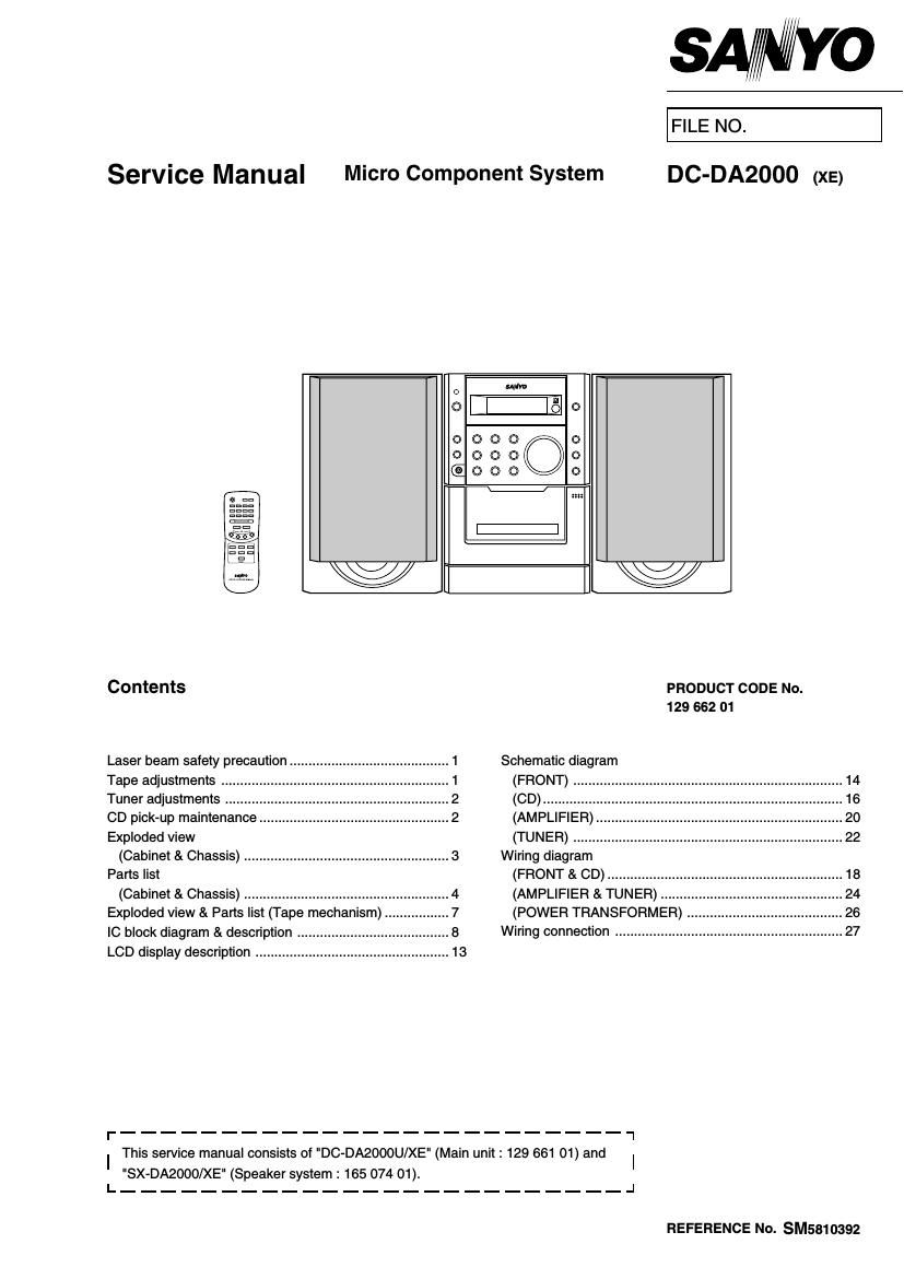
Service Manual Micro Component System DC-DA2000 (x5)

C) o

moo

xxx:

W] W

Contents PRODUCT CODE No.
129 662 01

Laser beam safety precaution 1 Schematic diagram

Tape adjustments .................. .. 1 (FRONT) ....................................................................... 14

Tuner adjustments .......... .. 2 (CD) ................ 16

CD pick-up maintenance. .. 2 (AMPLIFIER) .. 20

Exploded view (TUNER) ....................................................................... 22
(Cabinet & Chassis) ...................................................... 3 Wiring diagram

Parts list (FRONT & CD) ............ 18
(Cabinet & Chassis) ...................................................... 4 (AMPLIFIER & TUNER) .. 24

Exploded view & Parts list (Tape mechanism). .. 7 (POWER TRANSFORMER) . 26

IC block diagram & description ........................ .. 8 Wiring connection .................... 27

LCD display description ................................................... 13

r' _________________________ '1
I This service manual consists of "DC-DA2000U/XE" (Main unit : 129 661 01) and I

"SX-DA2000/XE" (Speaker system : 165 074 01).
L_ _________________________ _J

REFERENCE NO. SM5810392

Page 2

LASER BEAM SAFETY PRECAUTION

0 Pick-up that emits a laser beam is used in this CD player section.

CAUTION:
USE OF CONTROLS OR ADJUSTMENTS
OR PERFORMANCE OF PROCEDURES
OTHER THAN THOSE SPECIFIED HEREIN WHWLTHLV
MAY RESULT IN HAZARDOUS RADIATION -"

. .flll'ITflJi.l..
EXPOSURE . eiiJEEUH m:


LASER OUTPUT..
WAVELENGTH .....

..0.6 mW Max. (CW)
.. 790 nm

UM w

CAUTION e INVISIBLE LASER RADIATION WHEN OPEN AND
INTERLOCKS DEFEATED AVOID EXPOSURE To EEAM

ADVARSELr USVNLIG LASER STRALING vED ABNING. NAR
SlKKERHEDSAFERVDERE ER UDE AF FUNKTlON. UNDGA UDS IET'IELSE

FOR STRALING. ,

VARNlNG , OSVNLIG LASER STRALNING NAR DENNA DEL AR OFPNAD . .

OCH SPARR AR URKOPPLAD STRALEN AR FARLIG. , .

VORSICHTr UNSICHTEARE LASERSTRAHLUNS TRITIAUS, WENN ' 7 r: :3 CLASS 1 LASER PRODUCT
DECKEL GECFFNET UND WENN SICHERHEITSVERRIEGELUNS , LUUKAN 1 LASEHLNTE
UBERBRUCKT lST. NIGHT. DEM STRAHLAUSSETZEN. Kl-ASS 1 LASEHAPPAHAT
VARO , AVATTAESSA .IA SUOJALUKITUS OHITETIAESSA OLET ALTTIINA
NAKVMATTOMALLE LASERSATEILVLLE ALA KATSO SATEESEEN.

TAPE ADJUSTMENTS
1. Azimuth Adjustment


0 Be sure to clean the heads before attempting to make any adjustment.
- Be sure both channels (1 and 2) are the same level.
(Using a dual-channel oscilloscope)
0 Be sure both channel's waveform are same for the phase matching.
- After completion of the adjustment, use the threadlock (TB-1401 B) to
secure the azimuth adjustment screws.

Remove the cover deck as Fig.1.

Load a test tape (V'lT-738 etc. : 10kHz) in the Deck.

Press the PLAY button. (Normal playback)

Use a + tip screwdriver to turn the screw for normal azimuth

adjustment so that the left and right outputs are maximized at

the same phase during normal playback. See Fig.2.

5. Adjust so that the waveforms for the left and right channels are in alignment.

PFANT

Fig.2

2. Tape Speed Adjustment

. Connect the Frequency Counter to TAPE OUT. Q
1 hole for adjustment

. MOTOR Fi 3
Insert the test tape (MTT-t 1 1N, etc.; 3,000Hz) Into the DECK. 9'

Press the PLAY button. .
Adjust a hole on the motor bottom so that a frequency counter reading of 3,000 :5Hz is obtained.See Fig.3.
Press the STOP button, and eject the test tape.

PWNT

3. Torque Measurement

Item Take-up Torque Back tention Pully tention

Driving power cassette:

Test Cassette PLAY:TW2111A(FWD) PLAY:TW2112A(FWD)
TW-2412(PLAY)

PLAY/REV. 30~65 grcm 2~6 grcm >50 grcm

F.FWD/REW 55~14O grcm - -