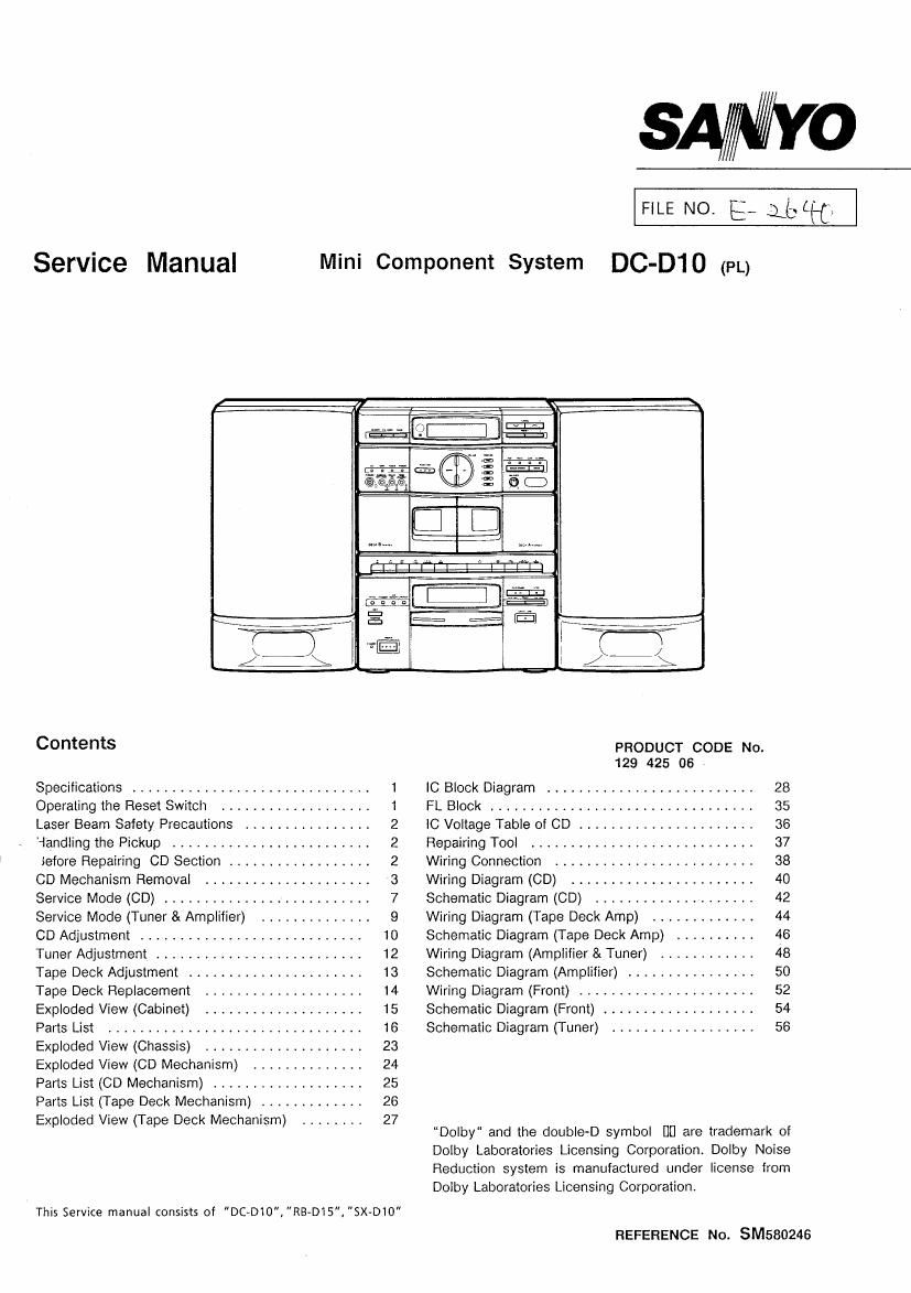
Sanyo dc d10 mini component system

This is the 40 pages manual for sanyo dc d10 mini component system.
Read or download the pdf for free. If you want to contribute, please mail your pdfs to info@audioservicemanuals.com.

Page: 1 / 40
left right
sanyo dc d10 mini component system

Extracted text from sanyo dc d10 mini component system (Ocr-read)


Page 1

SA/MYO

FILE NO. E_ 1ch

Service Manual Mini Component System DC-D10 (FL)

Contents pnooucr CODE No.
129 425 06

Specifications ............................. 1 IC Block Diagram .......................... 28
Operating the Reset Switch ................... 1 FL Block ................................. 35
Laser Beam Safety Precautions ................ 2 IC Voltage Table of CD ...................... 36
'iandling the Pickup ......................... 2 Repairing Tool ............................ 37
iefore Repairing CD Section .................. 2 Wiring Connection ......................... 38
CD Mechanism Removal ..................... 3 Wiring Diagram (CD) ....................... 40
Service Mode (CD) .......................... 7 Schematic Diagram (CD) .................... 42
Service Mode (Tuner & Amplifier) .............. 9 Wiring Diagram (Tape Deck Amp) ............. 44
CD Adjustment ............................ 10 Schematic Diagram (Tape Deck Amp) .......... 46
Tuner Adjustment .......................... 12 Wiring Diagram (Amplifier & Tuner) ............ 48
Tape Deck Adjustment ...................... 13 Schematic Diagram (Amplifier) ................ 50
Tape Deck Replacement .................... 14 Wiring Diagram (Front) ...................... 52
Exploded View (Cabinet) .................... 15 Schematic Diagram (Front) ................... 54
Parts List ................................ 16 Schematic Diagram (Tuner) .................. 56
Exploded View (Chassis) .................... 23

Exploded View (CD Mechanism) .............. 24

Parts List (CD Mechanism) ................... 25

Parts List (Tape Deck Mechanism) ............. 26

Exploded View (Tape Deck Mechanism) ........ 27

"Dolby and the double-D symbol DEI are trademark of
Dolby Laboratories Licensing Corporation. Dolby Noise
Reduction system is manufactured under license from
Dolby Laboratories Licensing Corporation.

This Service manual consists of DC-010","RB-D15,"SX-DIO"
REFERENCE No. SM580246

Page 2

SPECIFICATIONS

Note:

The below mentioned specifications are mainly based on the IHF measurements standard. They can therefore not directly be
compared with specifications based on the DIN standard or other standards.

DC-D10U MAIN UNIT
Tuner section
Reception frequency FM : 65 - 74 MHz, 875 ~ 108 MHz
MW :522- 1611 kHz

LW: 144 - 290 kHz

CD player section

Channels ............ 2~channel stereo
Sampling frequency 44.1 kHz
Pickup .............. Optical 3-beam

semiconductor laser
0.6 mW (Continuous wave max.)
790 nm
20 Hz - 20 kHz
Below measurable limits

Laser output ..........
Wave length ..........
Frequency response . . . .
Wow and flutter
Cassette deck section
Track system
Frequency response . . . .

4-track, 2-channel stereo

60 Hz - 14,5 kHz (Cr02 tape)
60 Hz - 13,5 kHz (Normal tape)
60 dB (Dolby NR ON)

0.1.5 9/: (WE-MS)

Signal to noise ratio

Wow and flutter

Fast forward /
rewind time(approx.)

110 sec. (0-60)

RB~D15 WIRELESS REMOTE CONTROLLER

Power requirements . . . . R6 (HP 7)" x2 batteries
Dimensions(approx.) . . . . 40 (W)X178 (H)x16 (D) mm
Weight(approx.) 859 (without batteries)

Amplifier section
Output power .........
Sound preset
input

Outputs

General
Power requirements
Power consumption
Dimensions(approx.) . . . .
Weight(approx.)

SX-D10 SPEAKER SYSTEM

Type ................
Unit used

Maximum power-
handling capacity .....
Nominal impedance
Dimensions(approx.) . . . .
Weight(approx.)

15 W x 2

(at 6 ohms 10% distortion)
4 electronic presets
PHONO : 2.5 mV / 50k ohms
SPEAKERS : 6 ohms
PHONES: 8 - 32 ohms

AC 230 V, 50 Hz

45 W

270 (W)x356 (H)><315 (D) mm
7 kg

2 way bass reflex
Woofer : 120m cone type
Tweeter : ceramic

30 W (peak)

5 ohms

200 (W)x356 (H)x205 (D) mm
2.7 kg (per speaker)

Specification subject to change without notice.

OPERATING THE RESET SWITCH

This unit is provided with a reset switch on the rear panel. The reset switch serves to initialize the microprocessor in the unit
which controls the CD, TUNER, TAPE DECK and AMP block. If the unit is to be serviced or key input is not acknowledged
even when the CD, TUNER, TAPE DECK and etc. operation buttons are pressed, press the RESET switch and initialize the

microprocessor following the step below.

1) . Disconnect the AC power cord from the power outlet.
2) . Keep the RESET switch depressed for 60 seconds.

(The backed up electrolytic capacitor is discharged by keeping the RESET switch depress.)

3) . Reconnect the AC power cord to the power outlet.

4) . Press the CD, TUNER, TAPE DECK and etc. operations, and check their operation.