Sanyo dc c50

This is the 9 pages manual for sanyo dc c50.
Read or download the pdf for free. If you want to contribute, please mail your pdfs to info@audioservicemanuals.com.

Page: 1 / 9
left right
sanyo dc c50

Extracted text from sanyo dc c50 (Ocr-read)


Page 1

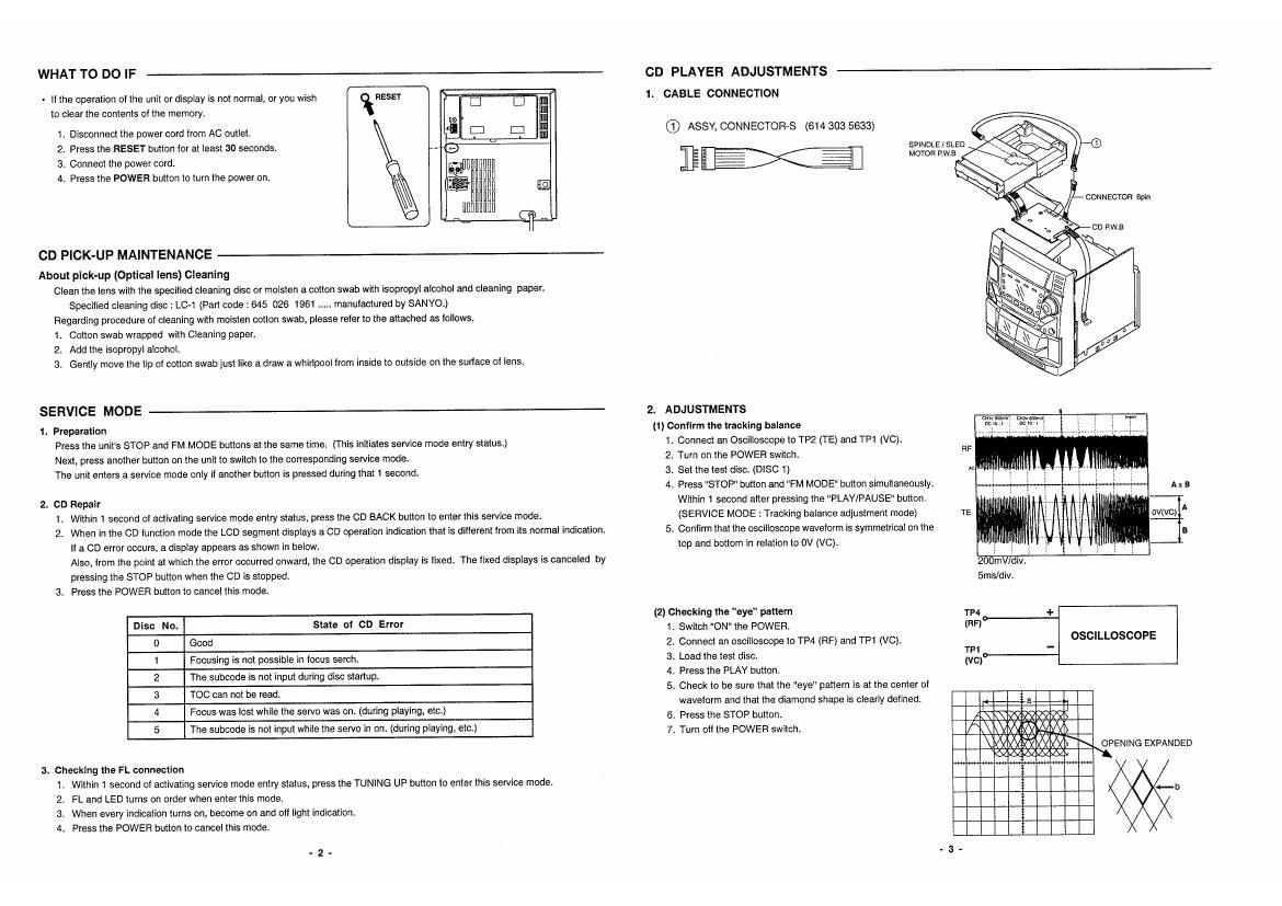
WHAT TO DO IF

- it the operation ol the unit or display is not normal. or you wish
to clear the contents ol the memory.

R ease-r
1. Disconnect the power cord irom AC outlet.
2. Press the RESET button tor at least 30 seconds. A
3. Connect the power cord.
4. Press the POWER button to turn the power on.

CD PICK-UP MAINTENANCE

CD PLAYER ADJUSTMENTS

About pick-up (Optical lens) cleaning
Clean the lens with the specified cleaning disc or moisten a cotton swab with isooropyl alcohol and cleaning paper.
Specified cleaning disc : LC-1 (Part code : 645 026 1961 ..... manuiactured by SANYO.)
Regarding procedure oi cleaning with moisten cotton swab. please raterto the attached as lollows.
1. Cotton swab wrapped with Cleaning paper.
2. Add the isopropyt alcohol.
3. Gently move the tip ol cotton swab just like a draw a whirlpool trom inside to outside on the surlace oi lens.

SERVICE MODE

1. Preparation
Press the unit's STOP and FM MODE buttons at the same time. (This Initiates service mode entry status.)
Next, press another button on the unit to switch to the corresponding service mode.
The unit enters a service mode only it another bmton is pressed during that 1 second.

2. CD Repair
1. within 1 second ol activating service mode entry status, press the CD BACK button to enter this service made.
2. When in the OD lunction mode the LCD segment displays a CD operation indication that is different trom its normal indication.
If a CD error occurs. a display appears as shown in below.
Also, from the point at which the error occurred onward. the CD operation display is Iixed. The lixed displays is canceled by
pressing the STOP button when the CD is stopped.
3. Press the POWER button to cancel this mode.

Disc No. State of On Error

Good

Focusing is not possible in locus serch.

The subcode is not input during disc startup.

TOC can not he read.

Focus was lost while the servo was on. (during playing, etc.)

Utwa-to

The subcode is not input while the servo in on. (during playing. etc.)

3. checking the FL connection
1. within 1 second of activating service mode entry status, press the TUNING UP button to enter this service mode.
2. FL and LED turns on order when enter this mode.
3. When every indication turns on, become on and all light indication.
4. Press the POWER button to cancel this mode.

.2.

CABLE CONNECTION

® ASSY, CONNECTOR-S (614 303 5633)

Slim

2. ADJUSTMENTS
(I) Confirm the tracking balance

1. Connect an Oscilloscope to TP2 (TE) and TPl (V0).

2, Turn on the POWER switch.

3. Set the test disc. (Disc 1)

4. Press "STOP" button and FM MODE" button simultaneously.
Within 1 second atter pressan the PLAY/PAUSE button.
(SERVICE MODE : Tracking balance adjustment mode)

5. Confirm that the oscilloscope waveform is symmetrical on the
top and bottom in relation to 0V (VC).

(2) checking the "eye" pattern

1. Switch ON" the POWER.

2. Connect an oscilloscope lo TP4 (RF) and TPt (VC).

3. Load the test disc.

4. Press the PLAY button.

5. Check to be sure that the "eye" pattern is at the center oi
wavelorm and that the diamond shape is clearly defined.

6. Press the STOP button.

. Turn oil the POWER swnoh.

V

SPlNDLE / SLED
MOTOR awe


RF

A = B
TE cvtvc) A

Ems/div.

TP4 +
(RF)
OSCILLOSCOPE

TF1 _
(VG)


OPENING EXPANDED

«.1»

Page 2

TAPE ADJUSTMENTS

1.

TAPE ADJUSTMENTS
2. MOTOR REPLACEMENT AND SPEED ADJUSTMENT

Adjustment item Test Tape Measuring Output connection Adjust Adjust
Instrument location value
(3) HEAD AZlMUTH V 738 etc. Avacltmeler SPEAKER TERMINAL HEAD AZIMUTH Max.
DECK "A (1 DKHZ) SCREW
(b) HEAD AZIMUTH V 733 etc. AC-valtrneter SPEAKER TERMINAL HEAD AZIMUTH Max.
DECK "E" (l OKHZ) SCREW
to) MOTOR SPEED M'IT-t ll FREQUENCY SPEAKER TERMINAL VR31 l 3.000Hz
(NORMAL) (3,000Hz) COUNTER

HEAD REPLACEMENT AND AZIMUTH ADJUSTMENT

(I) Head replacement

1. Alter replacement, demagnetize the heads by using a

degausser.

Be sure to clean the heads belore attempting to make any

adjustments.

8. Be sure both channels (1 and 2) are the same level.
{Using a dual-channels oscilloscope).

4. All wiring should be returned to the original position alter
work is completed,

N

(2) Head azimuth

- DECK "A1

1. Remove the lelt side ol CASSETTE LID.

2. Load a test tape (VTT-738.etc.: 10kHz) tor azimuth
adjustment.

3. Press the PLAY button,

. 4. Use a tlaHip (-) screwdriver to turn the screw tor normal

azimuth adjustment so that the lett and right outputs are
maximized at the same phase during normal playback.
5. Press the STOP button.

DECK "B"
. Remove the right side of CASSETTE LID.
. Load a test tor azimuth adjustment.
. Press the PLAY button.
. Azimuth screw adjustment.
. Press the STOP button.

album--

if ..
Willi m:

TAPE "a
N9 HEAD

- Afler making the adjustment, secure the azimuth
adjustment screw by applying screw lock (TB-1401B).

(1) Mater replacement

(2) Motor speed

I. Insert the test tape (MW-111 oretc. 3,000 Hz) into DECK A.

2. Press the PLAY button.

3. Adjust VR311 so that the lrequency counter shows reading
at 3.020 :10 HZ.

4. Press the STOP button.

. CHECKING THE MECHANISM TORQUES

TAPE SPEED
Amusmenr
vmn

. Clean the head, capstan and pinch roller before making any measurement.

DECK " A & B"
Measureent Takeup tuque aaektensm Tape tension
Cassette for PLAY : TW-2t11A PLAY ; 'rwrzt l lA Drive~power cassette
measurement we/new : TW»2231 TW»24l2
PLAY 25 «33 gm 2.0 - 6.0 gmn 70 or or more
F.FWD/REW so - t20 gran - -