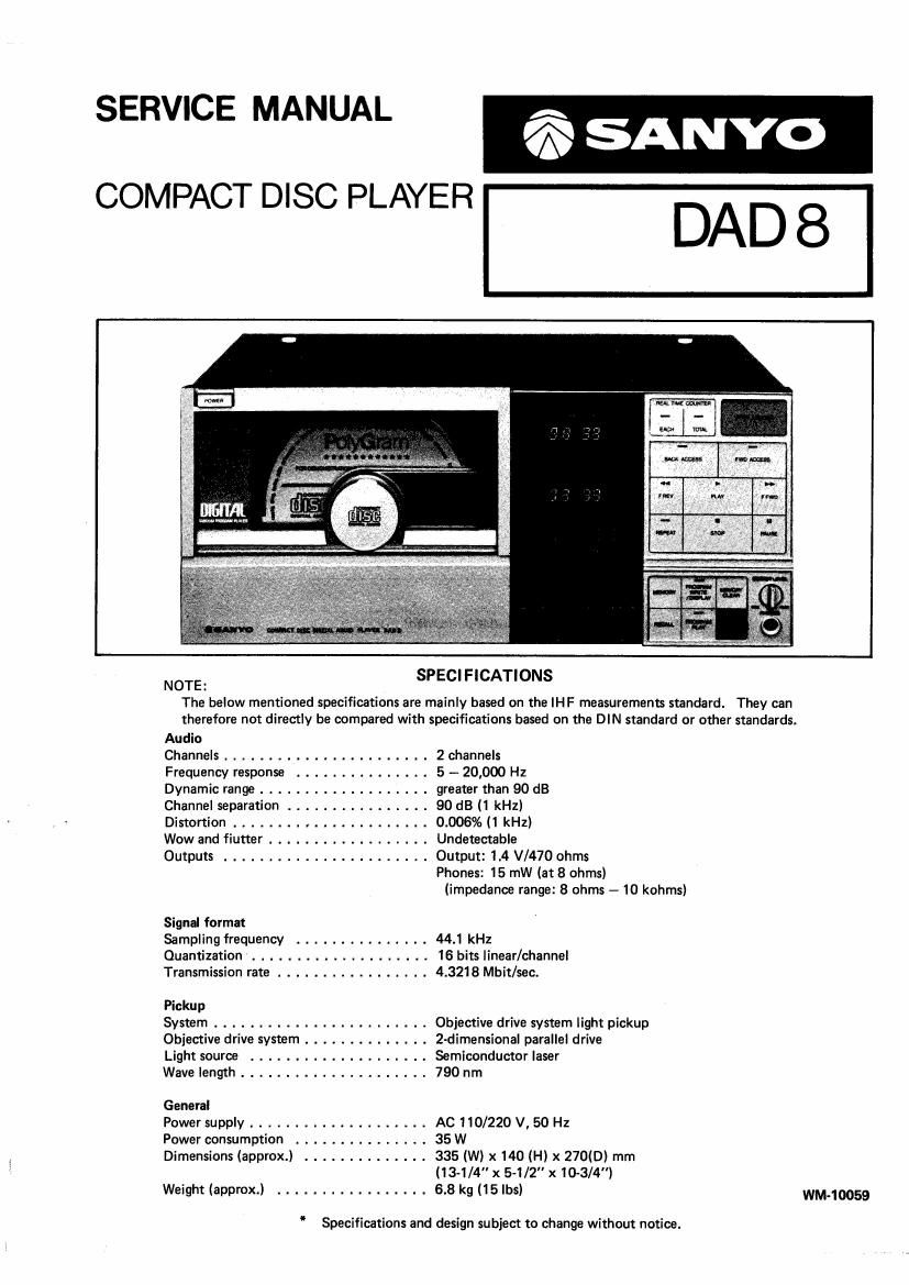
Sanyo dad 8

This is the 48 pages manual for sanyo dad 8.
Read or download the pdf for free. If you want to contribute, please mail your pdfs to info@audioservicemanuals.com.

Page: 1 / 48
left right
sanyo dad 8

Extracted text from sanyo dad 8 (Ocr-read)


Page 1

SERVICE MANUAL A
A

COMPACT DISC PLAYER

NOTE: SPECIFICATIONS

The below mentioned specifications are mainly based on the IH F measurements standard. They can
therefore not directly be compared with specifications based on the DIN standard or other standards.


Audio

Channels ....................... 2 channels

Frequency response ............. 5 - 20,000 Hz

Dynamic range ................. greater than 90 dB

Channel separation .............. 90 dB (1 kHz)

Distortion .................... 0.006% (1 kHz)

Wow and flutter ................ Undetectable

Outputs ....................... Output: 1.4 V/470 ohms
Phones: 15 mW (at 8 ohms)

(impedance range: 8 ohms - 10 kohms)

Signal format

Sampling frequency ............... 44.1 kHz

Quantization .................... 16 bits linear/channel

Transmission rate ................. 4.3218 Mbit/sec.

Pickup

System ........................ Objective drive system light pickup

Objective drive system .............. 2-dimensional parallel drive

Light source .................... Semiconductor laser

Wave length ..................... 790 nm

General

Power supply .................... AC 110/220 V, 50 Hz

Power consumption ............... 35 W

Dimensions (approx.) .............. 335 (W) x 140 (H) x 270(0) mm
(13-1/ x 5-1/ x10-3/4)

Weight (approx.) ................. 6.8 kg (15 lbs) WM-10059

" Specifications and design subject to change without notice.

Page 2

CONTENTS

1. SPECIFICATIONS .................................................... TOP COVER
2. HANDLING THE COMPACT DISC PLAYER .................................. 2
3. BEFORE REPAIRING THE COMPACT DISC PLAYER ........................... 3
4. HANDLING THE PICKUP ............................................... 4
5 LASER BEAM SAFETY PRECAUTIONS ..................................... 5
6. HOW TO DISASSEMBLE THE UNIT ........................................ 8
7. EXPLANATION OF THE COMPACT DISC (CD) PLAYER SYSTEM .................. 11
8. REPLACEMENT OF PICKUP AND SPINDLE MOTOR ............................ 14
9. PARTS LOCATION ................................................... 16
10. COMPACT DISC PLAYER ADJUSTMENTS ................................... 18
11. REPLACEMENT OF IC401 LM6402H ....................................... 31
12. PRINTED CIRCUIT BOARD CONNECTIONS ................................. 32
13. BLOCK DIAGRAM (FOR ADJUSTMENT) .................................... 34
14. CABINET EXPLODED VIEW ............................................. 35
15. CHASSIS EXPLODED VIEW ............................................. 36
16. PARTS LIST ........................................................ 37
17. MECHANISM EXPLODED VIEWS ......................................... 44
18. MECHANISM PARTS LIST .............................................. 46
19. BLOCK DIAGRAM ................................................... 47
APPENDIX

A-{
B.{
.{

SCHEMATIC DIAGRAM ® (DIGITAL/AUDIO/POWER SUPPLY) ................. NEW TYPE
WIRING DIAGRAM ® (PlCKUP/SERVO/SYSTEM CONTROL/DISPLAY) ........ NEW TYPE

SCHEMATIC DIAGRAM ® (PlCKUP/SERVO/SYSTEM CONTROL/DISPLAY) ........ NEW TYPE
WIRING DIAGRAM ® (DIGITAL/AUDIO/POWER SUPPLY) ................. NEW TYPE
SCHEMATIC DIAGRAM G) (DIGITAL/AUDIO/POWER SUPPLY) .................. OLD TYPE

WIRING DIAGRAM CD (DIGITAL/AUDIO) ............................. OLD TYPE
BLOCK DIAGRAM ...................................................