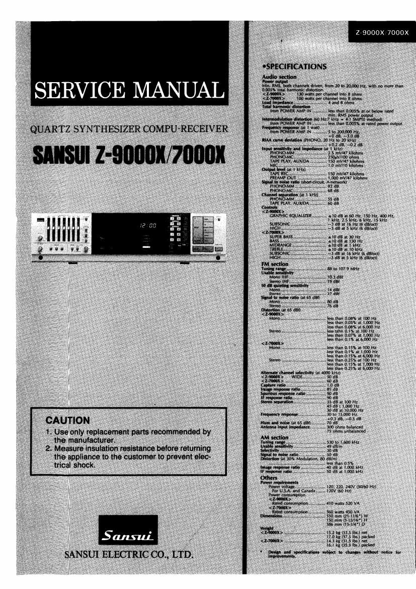
Sansui Z 7000X 9000X Service Manual

This is the 28 pages manual for Sansui Z 7000X 9000X Service Manual.
Read or download the pdf for free. If you want to contribute, please mail your pdfs to info@audioservicemanuals.com.

Page: 1 / 28
left right
Sansui Z 7000X 9000X Service Manual

Extracted text from Sansui Z 7000X 9000X Service Manual (Ocr-read)


Page 4

279000X17000X

2. ADJUSTMENTS

2-1. Reference Frequency Adjustment of Synthesizer Control Circuit
(See F-3810 Parts location on Page 11)

Note: 1. Input Selector ................................................ AM Fig. 2.1
2. TUNING/FM MODE ...... ., MANUAL/MONO W
3. Remove the Front Panel Assy and Sub Panel Assy. -
4. The frequency with mark is for the unit that the AMcnannnlnensw /
AM 9/10 kHz channel step switch (0526, See Fig. 2.1; pm. m... l

is set to 9 kHz and " is for the 10 kHz,
5. The unit without the AM 9/10 kHz channel step
switch is " mark frequency.

SUBJECT SETTING MEASURE OUTPUT ADJUST ADJUST FOR REMARKS
Xtal Set frequency display Between eTPZ (eC29) iTCl 1449kH1110Hz

Frequency to 999kHz and GNDa F-3806, (F3810) <**1450kHz*10Hz>

Adj, <*1000kHz> Frequency Counter

2-2. FM Adjustments
(See Fig.2-2, 2-4 and Top View on Page 17 and 18)

Fig. 2-2
Note: 1. Input Selector stenwsn
2. FM IF BAND.. 0|" min more
3. The frequency with W mark is for the unit that the 311556 umr LCN E 0
AM 9/10 kHz channel step switch (0526, See Fig. 2-1) of, mm W, A," liéizm ... rg org _g
is set to 9 kHz and is for the 10 kHz. more; 3 C ""D-I" HE *3
4 The unit without the AM 9/10 kHz channel step ' a
switch is " mark frequency. 3 c
1) FM IF
Note: 1. TUNING/FM MODE ................. MANUAL/MONO
FEED SIGNAL MEASURE
STEP SUBJECT FROM TO OUTPUT ADJUST ADJUST FOR REMARKS
ll FM IF Coil *98MHZ <*9B.1MHZ> ANT Between Point ® T1 MAX,
Adj, ANT Input ZOdBf terminal (le) and GND, (Front-end) DC Volt
(14.8dB), 1kHz 30011 DC Volt Meter
(100% MOD), FM SSG
2. Discriminator i 98MH2 Same as Between dTPi and dT2 0120mv
Coil Adj. < M98.1MHZ> above dTPZ, Across dR30 (F3806)
ANT Input 65 dBf (F3806)y
(59.8dB), ikHz DC Volt Meter
(100% MODJ,
FM 556
2 Same as above Same as REC OUT L-CH or dT3 Min. THD
above R-CH, (R3806)
VTVM & SCOPE/
Dist Meter
3 Si nal Level *98MHZ <*"98.1MH2> Same as SIGNAL Indicator clVRi Make only one / ='
A j. ANT Input 15dBf above (F3306) LED lighting y
(9.8dB), 1kHz i
(100% MOD), FM SSC slGNAL
0 Technical Hint for FM adjustment
' There are two kind in indication of FM 56 output attenuator. 0 The following table shows relations among FM 50 attenuator in,
1. Attenuator with marking of 759 open. open indication dlcation (dB), available power ratio (dBf) and antenna terminal
type. voltage (dB/uV) in each indication type.
2. Attenuator with marking of 75!? load or close load
or close indication type. FM 90 Available Antenna
0 FM SG output level in this FM adjustment are described as open Attenuator POW?" Terminal
indication typei indication Ratlo Voltage
' To feed FM signal, a dummy antenna circuit as Fig. 2-3 must be , , . 0 dB -0.8 dBf -6 dB/uV
connected between FM so output and ANT terminal (300m of the OPE" '"d'caw" We 66 dB 65.2 dBf 60 dB/uV
unit. . Load or close 0 dB 5.2 dBf O dis/v
Flg. 2-3 indication type 60 dB 65.2 dBf 60 dB/uV

Dummy antenna