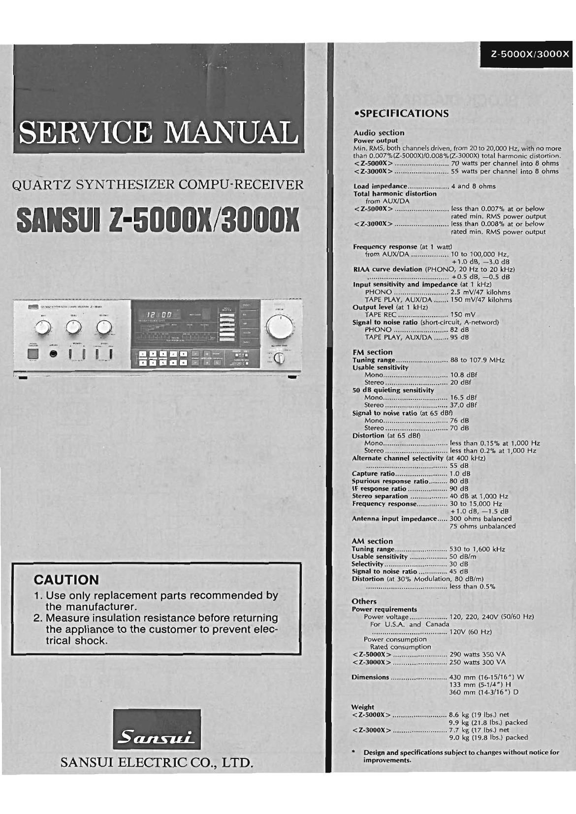
Sansui Z 3000 X Service Manual

This is the 19 pages manual for Sansui Z 3000 X Service Manual.
Read or download the pdf for free. If you want to contribute, please mail your pdfs to info@audioservicemanuals.com.

Page: 1 / 19
left right
Sansui Z 3000 X Service Manual

Extracted text from Sansui Z 3000 X Service Manual (Ocr-read)


Page 1

QUARTZ SYNTHESIZER COMPU-RECEIVER

SANSlll Z-50lllilll/3'ilflflli

CAUTION

1. Use only replacement parts recommended by
the manufacturer.

2. Measure insulation resistance before returning .
the appliance to the customer to prevent elec-
trical shock.

Salami.
SANSUI ELECTRIC CO., LTD.

Z-5000X/3000X

'SPECIFICATIONS

Audio section

Power output

Min. RMS, both channels driven, from 20 to 20,000 HZ, with no more
than 0007%(Z-5000X)/0.008°/a(Z-3000X) total harmonic distortion.

................... 70 watts per channel into 8 ohms
.......................... 55 watts per channel into 8 ohms
Load impedance .................... 4 and 8 ohms

Total harmonic distortion
from AUX/ DA
......................... less than 0.007% at or below
rated min. RMS power output
.. less than 0.008% at or below
rated min. RMS power output

< Z-3000X > ...................

Frequency response (at 1 watt)
from AUX/DA .................. 10 to 100,000 Hz,
+1.0 dB, -3.0 dB
RIAA curve deviation (PHONO, 20 Hz to 20 kHz)

....................................... +0.5 dB, -O.5 dB
Input sensitivity and impedance (at 1 kHz)
PHONO .......................... 2.5 mV/47 kilohms

TAPE PLAY, AUX/DA ....... 150 mV/47 kilohms
Output level (at 1 kHz)

TAPE REC ........................ 150 mV
Signal to noise ratio (short-circuit, A-netword)
PHONO .................... 82 dB
TAPE PLAY, AUX/DA ....... 95 dB
FM section
Tuning range ......................... 88 to 107.9 MHz
Usable sensitivity
Mono.... ............ 10.6 dBt
Stereo.. ......... 20 dBf
50 dB quieting sensitivity
Mono... ......... 16.5 dBf
Stereo ......... 37.0 dBf
Signal to noise ratio (at 65 dBf)
Mono.... ............ 76 dB
Stereo ............ 70 dB
Distortion (a
Mono.... ...... less than 0.15% at 1,000 Hz


Stereo... less than 0.2% at 1,000 Hz
Alternate channel selectivity (at 400 kHz)
....................................... 55 dB
Capture ratio ................ 1.0 dB

Spurious response ratlo 80 dB

IF response ratio.... 90 dB

Stereo separation 40 dB at 1,000 Hz

Frequency response ............... 30 to 15,000 Hz
+1.0 dB, -1.5 dB

Antenna input impedance ..... 300 ohms balanced

75 ohms unbalanced

AM section
Tuning range ......................... 530 to 1,600 kHz
Usable sensitivity 50 dB/m
Selectivity ............... 30 dB
Signal to noise ratio .............. 45 dB
Distortion (at 30% Modulation, 80 dB/m)
....................................... less than 0.5%
Others
Power requirements
Power voltage .................. 120, 220, 240V (50/60 Hz)
For U.S.A. and Canada
.................................... 120V (60 Hz)
Power consumption
Rated consumption
.......................... 290 watts 350 VA
.......................... 250 watts 300 VA
Dimensions ........................... 430 mm (16-15l16) W

133 mm (5-1/4) H
360 mm (14-3/16) D

Weight
.......................... 8.6 kg (19 lbs.) net

9.9 kg (21.8 lbs.) packed
.......................... 7.7 kg (17 lbs.) net

9.0 kg (19.8 lbs.) packed

"' Design and specifications subject tachanges without notice for
improvements.

Page 9

Z-5000X/3000X

0 Technical Hint for FM adjustment

I There are two kind in indication of FM 56 output attenuator. - The following table shows relations among FM 56 attenuator in-
i. Attenuator with marking of 759 open .......... open indication dication (dB), available power ratio (dBf) and antenna terminal
type. voltage (dB/IN) in each indication type.
2. Attenuator with marking of 750 load or close ............... load _
or close indication type. FM SC Available Antenna
. FM 56 l | . th' FM d' d 'b d Attenuator Power Terminal
. .output eve in Is a justment are escri e as open Indication Ratio Voltage
indication type. d d f
. To feed FM signal) a dummy antenna circuit as Fig. 4-3must be Open indication type 62 d3 Egg dgf ES 337?;
connected between FM SC output and ANT terminal (300(2) ofthe ' ' fl
unit. - Load or close 0 dB 5.2 dBf O dB/uV
indication type 60 dB 65.2 dBf 60 dB/uV
Fig. 4-3
Dummy antenna
4-3. AM Adjustments
(See Figs. 4-4, 4-5, Parts Location F3900 on page 11 and Top
View on Page 15) PRESET -AM-_
Note: 1. input Selector ................................................ AM KEY *9 kHz step 10 kHz step
2 TUNING/FM MODE ................. MANUAL/MONO 1 522 kHz 530 kHz
3. The frequency with * mark is forthe unit that the
AM 9/10 kHz channel step switch (0529, See Fig. 4-1) 2 1611 kHz 1620 kHz
is set to 9 kHz and **" is for the 10 kHz. 3 y 603 kHz 600 kHz
4. AM channel step frequency of the unit without the
AM channel step switch (0529) is fixed to 10kHz, and 4 1404 kHZ 1400 kHz
it is applicable to the USA (UL) and Canada (CSA)
under industrial standards. F'
. - - ig. 4-4
5. Preset the listed frequenCIes to the memories. VTVM scope
AM SSG UNIT
O
c .___ A ANT Rea _____\ lg oucr fa. g
o__T""'L_i_o j""1__° °._Y"L_°
(1) AM IF
Fig. 4.5 GENESCOPE
FEED SIGNAL MEASURE
STEP SUB ECT AD UST AD UST FOR REMARKS
FROM TO OUTPUT l J
1. IF Coil Adj. Genescope Output Point ® Between Point © eCFi, MAX. m
SOdB (eRT), (eRi i) and Earth, (F3900) Waveform
F3900 F-3900
2) AM Tuning Voltage
STEP SUBJECT SETTING MEASURE OUTPUT ADJUST ADJUST FOR REMARKS
i. *SZZkHz Depress PRESET Key Between (8) and Earth, eT2 1V3:O.iV 'Repeat procedures as
<**530kHz> i to readout 522kHZ F3900, DC Volt Meter (F3900) state in STEP 1 Br 2.
Tuning Voltage < **530l >
2. *1611kHz Depress PRESET KeK Same as above eTC2 9V3:0.iV
<*l620kHZ> 2 to readout *1611 Hz (F-3900)
Tuning Voltage < i 620kHz>