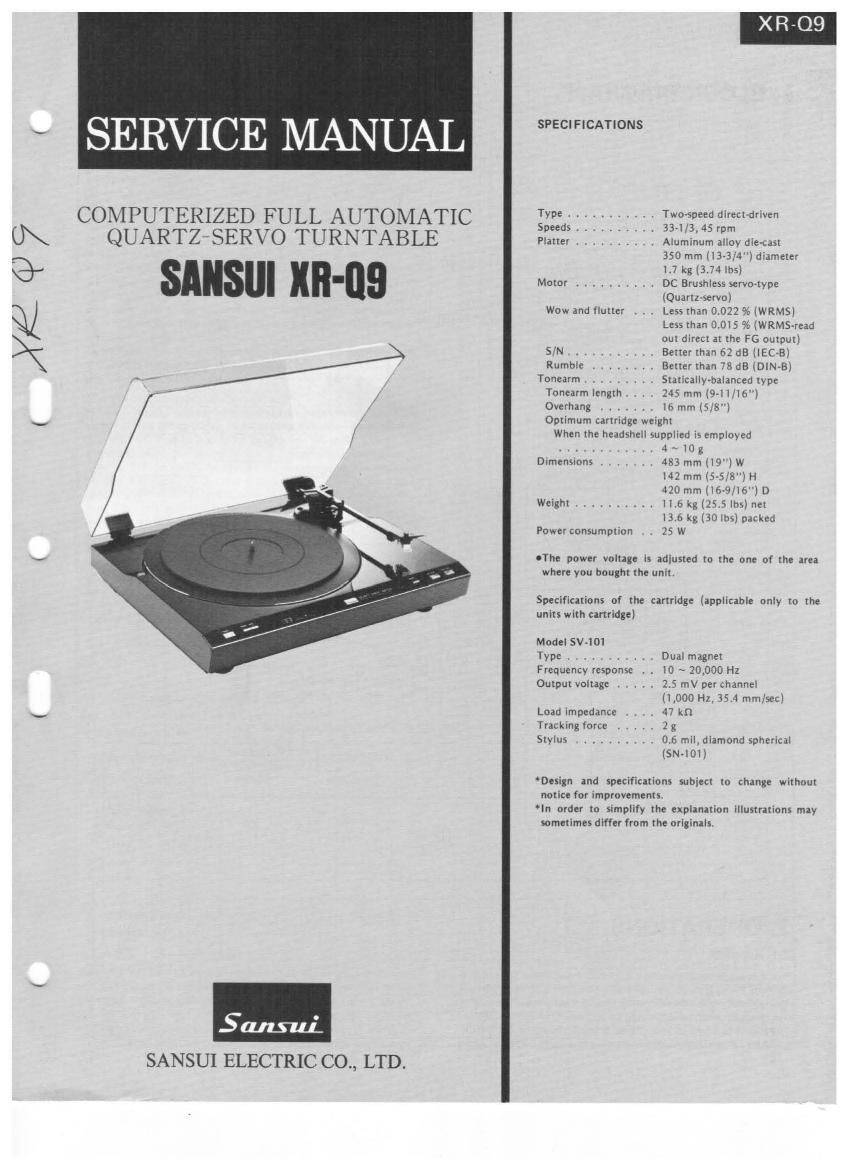
Sansui XR Q9 Service Manual

This is the 25 pages manual for Sansui XR Q9 Service Manual.
Read or download the pdf for free. If you want to contribute, please mail your pdfs to info@audioservicemanuals.com.

Page: 1 / 25
left right
Sansui XR Q9 Service Manual

Extracted text from Sansui XR Q9 Service Manual (Ocr-read)


Page 1

SERVICE MANUAL

COMPUTERIZED FULL AUTOMATIC
QUARTZrSERVO TURNTABLE

Sauna:
SANSUI ELECTRIC CO., LTD.

SPECIFICATIONS
Type .......... Two-speed directorlven
Speeds .......... 33-1/3, 45 rpm
Platter .......... Aluminum alloy die-cast
350 mm 1133/4") diameter
1.7 kg (374 lbs)
Motor ......... DC Brushless servo-type
(Quartzservol
Wow and flutter , V . Less than 0.022 % (WRMS)
Less than 0.015 % (WRMS-read
out direct at the F6 output)
S/N ........... Better than 62 dB (lEC-B)
Rumble ........ Better than 78 dB [DIN-B)
Tonearm ......... Statically-balanced type

Tonearm length. , t 245 mm (9-l l/16")

Overhang ....... l6 mm 15/8")

Optimum cartridge weight

When the headshell supplied is employed
............ 4 ~ 10 g
Dimensions ....... 483 mm (19") W

142 mm (5-5/8") H
420 mm (l6-9/l6") D

Weight .......... .6 kg (25.5 lbs) net
13.6 kg [30 lbs) packed
Power consumption . . 25 W

UThz power voltage is adjusted to the one of the area
where you bought the unit.

Specifications of the cartridge (applicable only to the
units with cartridge)

Model SV-1OI

Type ........... Dual magnet

Frequency response . t io \ 20,000 Hz

Output voltage ..... 25 mV per channel
(1,000 Hz 35.4 rum/sec]

Load impedance , t , . 47 kn

Tracking force . 2 g

Stylus .......... 0.6 mil, diamond spherical
(SN-101)

Design and specifications subject to change without
notice for improvements

In order to simplify the explanation illustrations may
sometimes differ from the originals.

Page 2

1. BLOCK DIAGRAM

i
I


I X-TAL l
4 I6 TRII W
I START 5T.» 8 REPEAT IND
, 5 l'l TRIz
l LIFTER DRIVER B I'TCTTI. IND
3 [8 TRIS .w
I REPEAT 2 I604 DRIVER 8 sum. IND
FPD 554C 25-_|
I A SENSOR H 10o. ICOSD
LOGIC 22 REPEAT
CIRUIT MICRO DELAY
B SENSOR ll COMPUYER 20
END
DETECT l0 lCozc.d
TRnI 23 ASTABLE w,
c sansoa II :: }')HULTWIBRATDR 6 ICSEIPUTER
24
mos Tfiow I
DISC SE 1009 a mmanorun MICROMIJTUR I
LECTDR I'- ONINERTIA CONTROL
__ FLIP-FLU? m r
1 I 0030 g I 2 MICROMGTDR
fifi-r
ED SELECTOR » FL|P-FLOP_ CCWINERTIA
RESET MICROHOTIR
2 l3 TRMno
PLUNGER PLUmER
ICosa DRIVER - SOLENOID
RESET
It + 5 FLIP-FLOP
Tam! TRIo~Is
STRDBO w.
0mm -> a sweat: LAMP 0° MOTOR I
Tst DRIVE CIRCUIT I
TRM 2| I
% 35, 5 H |Co4 PICANP 7-» Icosa [cosh
SELECTON CXIQS TRoq AUDER fi G PI !
,LTROfi 5 PH AMP CIRCUIT I
F/V SPEED I
CONTROL
PULSE UETE 8 vomee
-CTING HEAD INVEm ronpmrm osc
ICosD ICosa CIRCUIT
REVERSE LE- 1 6
TECTINGHEAD
TRI£~II
1- X-TAL -l
2. OPERATIONS
2-1. General
This automatic turntable uses a microcomputer in the same way as used in the DD motor servo system, in order to keep the revolution
FR-D4/FROS; accordingly, the DD motor start/stop operation and speed constant at all times against various load fluctuations by pro-
the tone arm operation are automatically controlled A new lifter viding a high rate servo control. In addition to these operation
function (th 7" can be moved D and down independently in 3" features, the antomatic turntable is of a howlingvroof floating
operations) is provided in addition to the functions of FR-D4/FR- structure type, thereby improving the sound quality in association
()5, Also, a newly-developed normal/reverse torque servo circuit is with a light-weight, Dyna-optimum-balanced-straight tonearm.
1

Page 6

3. ADJUSTMENTS

3-1. Auto-Return Adjustment

1. Adjustment of slit plate fitting position

Temporarily fix the slit plate to the tonearm axle as illustrated in
Figs. 3-1 (A) and (B) with the tonearm kept positioned on the arm
rest.

2. Adjustment of B sensor output

1) Connect oscilloscope leads across the TP01 and the (END and set
the DC/AC selector switch to DC and the test ranges to lV/div.
and l msec./div.

2) With the tonearm kept positioned on the arm rest, first rotate
the VRoz (5-0048) clockwise, next slowly rotate it counter-
clockwise, and then stop it just before an increase in the TPD.
voltage is saturated. In this case, set the TPm voltage so as to be
3.8V or more.

3) Set the oscilloscope test ranges to lV/div. and 0.l sec/div. Bring
the tonearm to the lead-in groove portion on a record by hand.
and slowly move it right and left so that it may take about 2
seconds to pass the slit C in Fig. 3-l (B) through between the
LED and the phototransistor.

4) If the TPm output isa sine wave without any clipping distortion
and the peak-to-peak value is:

l less than 2.2V,
adjust it to 2.2V by rotating the VRM (5-0045).

2. if it is impossible to adjust it to 2.2V,or clipping distortion is
still observed,
move the slit plate in a direction (ED in Fig. 3-1 (A), and
adjust it again beginning from step i

3. more than 2.2V,
move the slit plate in a direction 6) in Fig. 3-1 (A), and
adjust it again beginning from step 1 .

5) After the above adjustment, make sure that the TPM voltage is

3.8V or more with the tonearm kept positioned on the arm rest,
before fixing the slit plate.

Fig. 3-1 Installation of Screen Plate
(Side View at Screen Plate

- ' man» has:


5r inn plate 7

' E
l \

Dec-d Se'sor Ass .

(B)Bottom View 04 Screen Plate
Note Tonearm IS placed on at: rest
Screen Plate

onn pl Methamsm assy

Fig. 3-2 Output Waveform Adjustment on B-Sensor
5 /_\ IT

A ML. )1 "0

Adjust the waveform on display as 3

3-2. Lead in Adjustment

By using 30 cm and 17 cm sized records having a narrow lead-in
groove portion, actually carry out the lead-in operation. Adjust the
adjust cam 43 [See Exploded View of Mechanism Ass'y on Page ii)
so that the stylus tip may come down to the middle of the lead-in
groove. Be sure that the slit plate is fit to the tonearm as shown in
Figs. 3-l (A) and (E). In this case, if the stylus point is required to
be led-in outside, rotate the adjust cam clockwise.

3-3. Repeat Adjustment

By using 30cm and I7 cm sized records having a narrow lead-in
groove portion, actually carry out the repeat operation. Adjust the
VRM (5-0046) so that the stylus tip may come down to the middle
of the lead-in groove portion.

3-4. Rev. Speed Adjustment (PLL adjustment)

Note: I) Make sure to carry out the speed adjustment at 45 rpm
before carrying out the speed adjustment at 33 rpm.
2) Make sure to carry out the adjustment with a rubber sheet
on.

A. How to adjust with an oscilloscope

l) Connect oscilloscope leads across the Tsz of 5-0038 and the
GND. and set the test ranges to 2V/div. and 0.5 msec./div.

2) Set the speed selector to 45 rpm.
Adjust the oscilloscope waveform to the one shown in Fig. 3-3
(A) by rotating the VRM (5-0038). In this case, make the pulse
width as narrow as possible.

3) Set the speed selector to 33 rpm.
Adjust the oscilloscope waveform to the one shown in Fig, 3-3
(A) by rotating the VRO (5-0058).

Fig. 3.3

(A) correct waveform

l j l

(B) incorrect waveform
l ll

(irffli

Adjust the pulse width as narrow as possible.

B. How to adjust without an oscilloscope

1) Set the speed selector to 45 rpm.
Bring the strobe pattern movement to a stop, by rotating the
VR01(S-0038).

2) Set the speed selector to 33 rpm.
Bring the strobo pattern movement to a stop, by rotating the
VRm (5-0038).

3-5. Electronic Brake Adjustment

Connect DC volt meter leads across the TPM and the TPOS, then
make the set operate. Adjust the voltage across the TPM and the
T? to 0.55V, by rotating the VR03 (5-0038).

3-6. Platter Height Adjustment

1) Place the turntable set horizontally.

2) Adjust the front, right, and left sides of the platter and the cabi-
net as shown in Fig. 3-4, by rotating the screw No. 8 (See Top
View on Page 9). In this case, a height difference among the
front, right and left must be within 1 mm.

Fig. 3-4