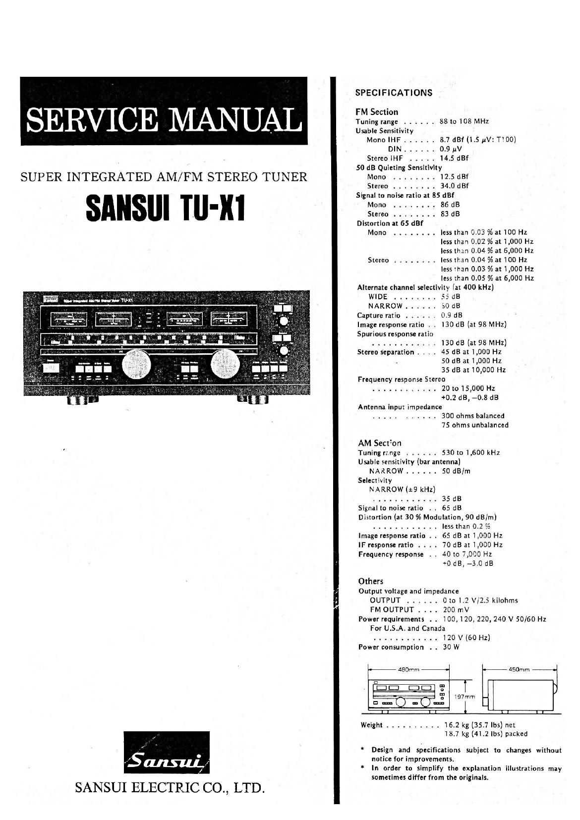
Sansui TU X1 Service Manual

This is the 19 pages manual for Sansui TU X1 Service Manual.
Read or download the pdf for free. If you want to contribute, please mail your pdfs to info@audioservicemanuals.com.

Page: 1 / 19
left right
Sansui TU X1 Service Manual

Extracted text from Sansui TU X1 Service Manual (Ocr-read)


Page 1

SPECIFICATIONS

FM Section
Tuning range ...... 88 to 108 MHz

Usable Sensitivity

MonolHF ...... 8.7 dBf(l.S uV1T00)
DIN ...... 0.9 uV
Stereo lHF ..... l4.5 dBf
50 dB Quieting Sensitivity
SUP ER INTEGRATED AM/FM STEREO TUNER giono ........ gig :3:

Signal to noise ratio at 85 dBf
- Mono ..... . . . 86 dB
. Stereo ........ 83 dB

Distortion at 65 dBf
Mono ........ less than 3.03 % at 100 Hz
less than 0.02 % at 1,000 Hz
less than 0.04 % at 6,000 Hz
Stereo ........ less than 0.04 % at 100 Hz
less mm 0.03 % at 1,000 Hz
less than 0.05 % at 6,000 Hz
Alternate channel selectivity (at 400 kHz)

a

W '*' Labiawb' WIDE . . . . . . .. 55 dB
NARROW ...... so dB
Capture ratio ...... 0.9 dB

Image response ratio , . 130 dB (at 98 MHz)
Spurious response ratio
............ 130 dB (at 98 MHz)
Stereo separation . . . . 45 dB at 1,000 Hz
50 dB at 1,000 Hz
35 dB at 10,000 Hz
Frequency response Stereo
............ 20 to 15,000 Hz
+0.2 dB, -0.8 dB
Antenna input impedance
........... 300 ohms balanced
75 ohms unbalanced

AM Section
Tuning range ...... 530 to 1,600 kHz
Usable sensitivity (bar antenna)
NA.{ROW ...... 50 dB/m
Selectivity
NARROW (19 kHz)
............ 35 dB
Signal to noise ratio . . 65 dB
Distortion (at 30 % Modulation, 90 dB/m)
............ less than 0.2 $5
Image response ratio . . 65 dB at 1,000 Hz
IF response ratio . . .. 70 dB at 1,000 Hz
Frequency response . . 40 to 7,000 Hz
+0 dB, -3.0 dB
Others
Output voltage and impedance
OUTPUT ...... 0 to L? V/Z.5 kilohms

FM OUTPUT . . .. 200 mV

Power requirements . . 100,120,220, 240 V 50/60 Hz
For U.S.A. and Canada
............ 120 V (60 Hz)

Power consumption . . 30 W

480mm 450mm
:3
El: [31: '2
El? 5' i97rnm
C] en: a m
I I I L I I l 1
Weight .......... 16.2 kg (35.7 lbs) net

18.7 kg (41.2 lbs) packed

Design and specifications subject to changes without
notice for improvements.

in order to simplify the explanation illustrations may
sometimes differ from the Originals.

SANSUI ELECTRIC CO., LTD.

Page 2

1. BLOCK DIAGRAM 2. OPERATION

V TU-XI employs PLL synchronized product detector in AM section

.5 and group delay equalizer, band-width selector using SAW filter,
5 and wide-range power ratio detector in FM section to improve S/N
i ratio and distortion.
- w a _I .1 ,.. .
.é éggga O AMsectIon
g g a E ii E The broadcast signal from antenna is applied to RF amp (FET 01)
O O


and mixed with OSC signal at IC02, then becomes 455 kHz IF signal
after passing through T02. After amplified by the differential amp
next to T02, one of the IF signal is fed to RF amp at first stage as
an AGC signal to control the gain through 001 D02, the voltage
doubler.

The other IF signal is branched and one is applied to signal meter,
and the other is supplied to phase shifter composed of R62, VR07,
R63, R64, and C36.

The IF signal to phase shifter is also devided into a signal toward
PLL synchronized product detector, and a signal to TR08, 09 after
amplified by TR07.

The signal through TR08, 09 is applied to photo-coupler (PC01) and
controls feed-back amount from TR07 to the differential amp com-
posed of TROS, 06 as AGC function by photo-coupler.

By the phase-shifter, 1r/4 advancing signal than IF signal is applied to
pin 4 of IC02, and 1r/4 lagging signal to pin 4 of IC03, where the
function of IC02 is synchronized detector to detect IF signal, and
IC03 is phase detector to obtain VCO signal sinchronized with IF
signal necessary for synchronized detection and constitutes PLL-
loop with VCO composed of TR14, Ii, 12. The signal input to pin

4 of IC02 is output from pin 12 as AF signal after synchronously
detected.

1. AM PLL SYNCHRONIZED PRODUCT
DETECTION

As shown in Fig. 2-1 (a), the spectrum of AM signal is composed of
upper & lower side-bands to be centered on the carrier "fc".

. The side-bands locate further from carrier fc" if modurating fre-
( quency becomes higher. Supposing carrier frequency "fc" as IF fre-
i quency 455 kHz, and generating a signal with the same frequency &
: phase as IF signal, the result of IF signal mixed with VCO signal is as
i

I

I

I

I

to SI} or Slla

5M
®-ioSIle or 5|!

I
RELAY
RL OI

SOID

288

LPF

50M

MPX ICSOI

SlO
ILSBI


C

"u
N

q

0C AMP

IUSB+LSSI
lUSB-LSBI

JMIITINGl
1
I
L

GROUPDE LAY
EOUALIZER

LFF
"LI
"L:
N
W

ocrtcron _ 'v

follow.

Generally, when a signal with frequency "fo" is mixed with a cer-
tain frequency signal "f, , signals f0 if," appear resultly. There-
fore when mixing IF signal fc :fm" [Fig. 2-1 (a)] with VCO signal
[Fig. 2-1 (b)] synchronized to the IF signal, AM signal centering
fc + fm (= 2fc)" with side-bands tfm. and +fm (upper side-band),
-fm (lower side-band) will appear as shown in Fig. 2-1 (c).

In conclusion, if +fm or "-fm is taken out somehow, the
modulating signal (Audio signal) will have been reproduced.
Further, PLL synchronized product detection allows AM reception
of wide range without interference because it is not necessary to
pick out the desired frequency by BPF at IF stage as conventional
emveloop detection.

Fi . 2-1
are E] a) l I

C 09)
WWW "'
DETECTOR __

ilC 02]

PHASE
V C 0

LIMIITER

L+ 65'
L45
I
I
I
l
I
I
l
I
L

$45
PHASE
SHIFYE fl

BPF

Li
"J

AM SECTION

FM SECTQII_

LIMITTER
AMP

DI.
AMP
A G C a
TI
METER
we" 5mm

%
"v

MULTIPA'IM DETECTOR

SPF

LIMITTER
(WIDE)
MP

(NARROW
A

DIFF
a P F AMP

apr IF All?

ic-Im fc fc+im
Spectrum of AM wave

MIX

b)

711;}! osc

I l

(V
V00 signal synchronizing to Phase & Frequency of AM wave

RF AMP

I I

_.__-_-l-l
I

69

us MIX
14 AMP (cm)
I ,
:F otsc
.

l.-- _._/...I
I
L-L--__...-_--

I I

fc-fv ic-Hv
fc-Irri+fv lic+fm+lv

LPF
71.,"
~

|Ic+irn-fv= +lrn
lIc-Im-rv= -fm
Spectrum when mixing a) 8: b)

2. AM SYNCHRONIZED DETECTION & PLL

For synchronized detection of AM signal, it is required to mix a
c 4 signal having the same frequency & phase with AM signal that TU-

I

c) 0

I
I

fly: I;

l- o-.
[W
15n@-l I

898

FM ANT
r 0-
soon
Em
All AMT

Page 19

8. PACKING LIST . 9. ACCESSORY PARTS LIST

Parts No. Stock No. Description Stock No. Description
1 9116800 Vinyl Cover 9203860 Operating Instructions
2 9028310 Styrofoam Packing , 38107.80 PJP Cord
3 9001591 Carton Case 3820120 FM Antenna
4 9019610 Corrugated Paper, Protector 99157-29 Antenna Coupler
' 2440021 F Type Connector
9238010 Schematic Diagram

SANSUI ELECTRONICS CORPORATION: 1250 Valley Brook Ave. Lyndhursz, NJ. 07071 USA.
' 333 West Alondra Blvd. Gardcna, California 90247 USA.
3036 Koapaka St. Honolulu, Hawaii 96819 u.s.A.
SANSUI AUDIO EUROPE N.V.: North Trade Bldg (9th lloor) Noorderlaan l33-Bus 1,2030 Antwerp, Belgium
SNASUI AUDIO EUROPE S.A.: Arabella center, 6 Frankfurt AM Main, Lyoner Strasse 44-48: West Germany
SANSLI ELECTRIC COMPANY LTD.: 14-], lzumi 2-chome, Suginamiku, Tokyo 168 Japan PHONE: (03) 323-11ll/TELEX: 232-2076

Printed by: Schaltungsdienst Lange, Berlin (GERMANY) SM135 (797230Ml