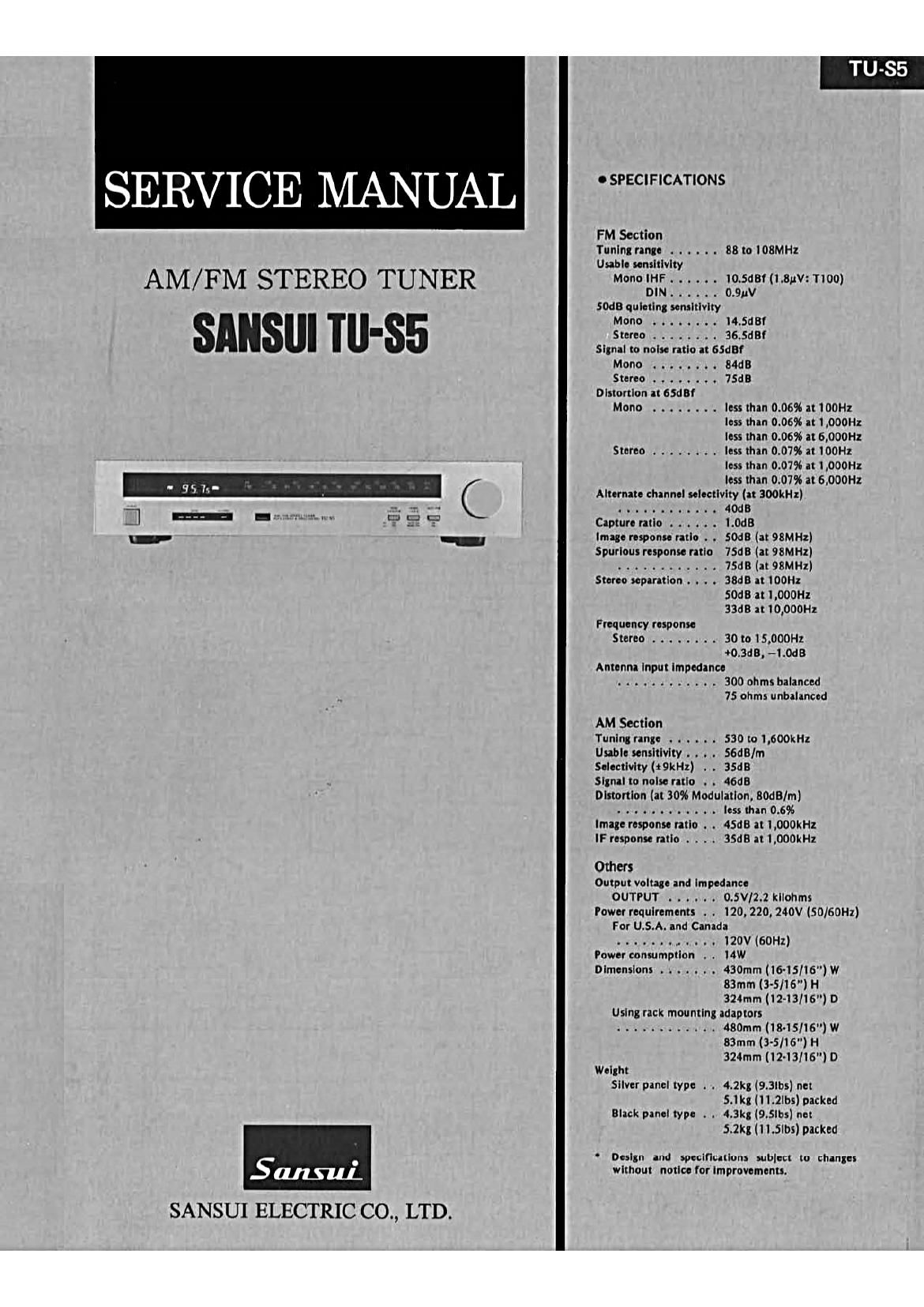
Sansui TU S5 Service Manual

This is the 8 pages manual for Sansui TU S5 Service Manual.
Read or download the pdf for free. If you want to contribute, please mail your pdfs to info@audioservicemanuals.com.

Page: 1 / 8
left right
Sansui TU S5 Service Manual

Extracted text from Sansui TU S5 Service Manual (Ocr-read)


Page 1

SERVICE MANUAL

AM/ F M STEREO TUNER

SANSUI Ill-85

SANSUI ELECTRIC CO., LTD.

0 SPECIFICATIONS

FM Section
Tuning range . . . . . . 88 to 108MHz
Usable sensitivity
Mono IHF. . . . . . iO.5dBf(i.8uV:Tloo)
DIN. . . . .. 0.9uV
SDdB quieting sensitivity

Mono ........ i4.5d8f
Stereo ........ 36.5dBf
Signal to noise ratio at as!
Mono . . ...... 84GB
Stereo ....... . 7Sd8
Distortion at 65d8f
Mono ........ less than 0.06% at iOOHz

less than 0.06% at 1,000Hz
less than 0.06% at 6,000Hz
Stereo ........ less than 0.07% at lOOHz
less than 0.07% at LOOOHI
less than 0.07% at 6,000Hl
Alternate channel selectivity (at 300kHz)
. .......... . 40dB
Capture ratio ...... l.0d8
Image response ratio . . SOdB (at 98MHz)
Spurious response ratio 75dB (at 98MH1)
. . . . . . 75dB(at98MHz)
Stereo separation . . . . 3868 at iOOHz
50:13 at l,000Hz
3368 at 10,000Hl
Frequency response
Stereo ........ 30 to 15.000Hz
+0.3d8, -i.0dB
Antenna Input impedance
... . . . . . . . .. 3000hmsbalanced
75 ohms unbalanced

AM Section

Tuning range . . . . . . 530 to 1,600kHz

Usable sensitivity . . . . SGdB/m

Seiectivity(t9kHz) . . 3SdB

Signal to noise ratio . . 46d8

Distortion (at 3096 Modulation, 80d8/m)
....... . . . . . less than 0.6%

image response ratio . . 45:18 at 1,000kHl

IF response ratio . . . . 35d8 at i,000kHz

Others
Output voltage and impedance
OUTPUT ...... 0.5VI2.2 kilohms

Power requirements . . 120,220,240V (50/60Hz)
For U.S.A. and Canada
..... . . . . . I20V(60Hz)
Power consumption . . MW
Dimensions . . . . . . . 430mm(i6-15/16)W
83mm (3-5/16") H
324mm(12-13Ii6) D
Using rack mounting adaptors
............ 480mm(18-15/16")W
83mm (3-5/16") H
324mm (1 2-I3/I6") 0
Weight
Silver panel type . . 4.2k3(9.3lbs) net
5.i kg (l l.2lbs) packed
Black panel type . . 4.3kg (9.5ibs) net
5.2K: (i 1.5lbs) packed

Design and specifications subject to changes
without notice for improvements.

Page 3

2. OPERATIONS

There are many specifications to decide what is excellent Tuner. In
specifications, both Signal to Noise Ratio (SM) and Distortion can
be the most important factors.

On conventional Tuner, RF and IF amplifier circuits occupy large
factor to secure high SIN and low distortion. This means that these
circuits must be all highly graded, and it concerns cost-up.

Sansui TU-SS adopts new Pulse-count Detecting circuit. The adop-
tion of this circuit minimizes the influence which RF and IF ampli-
fier circuits exercise SN and distortion. The values of these two
specifications are mostly decided by the Pulse-count Detecting cir-
cuit. Therefore, even midium graded Tuner can prove high S/N and
low distortion as high graded Tuner has.

The Pulse-count Detecting circuit comprises a frequency converter
and a pulse-count detector.

The reason why the frequency converter is adopted to the pulse-
count detector, is as follows.

The specifications of the pulse-count detector are decided by rise
time and stability of pulse width, of generated pulse by one-shot
multivibrator in the pulse-count detector. Therefore, if an input
frequency to the multivibrator is toohigh, it is impossible to obtain
high SN and low distortion. To avoid this problem, the input fre-
quency must be converted to a lower frequency which the multi-
vibrator is able to follow it.

The followings are the circuit operations of the pulse-count detect-
ing circuit on TU-SS.

Fig. 2-1

M51672P

i j
107MHz _ BALANCED lO.7+9.44MHz 4MHz 126MHz
IF IN MIXER LPF -¢'

' fl-
9.44MH2 OPAMP ' _
H osc , I MULTI

@1.26MH2 IF SIGNAL W
@OUTPUT OF LIMITER W
©THIGGER SIGNAL | |

®0UTPUTOFMULTIVIBRATOR | | I H |

@rAUDlO SIGNAL fl

TU-S5

1. Frequency converter (M51672P)

Frequency converter lC, M51672F has a differential amplifier and a
balanced mixer as Fig. 2-1. The differential amplifier works as a
local oscillator by connecting an external 05C coil, and the output
signal of the local oscillator is supplied to the balanced mixer. This
signal and IF signal from IF amplifier are mixed together in the
balanced mixer, and this mixed signal is outputted to a Iow~pass
filter. Then frequency conversion is completed after required fre-
quency signal from the pulse-count detector is selected by the low-
pass filter.

The frequency of the local oscillator is 9.44 MHz. And by mixing
10.7 MHz IF with it, two frequencies of 10.7 MHz 29.44 MHz are
outputted from the balanced mixer. However, only 1.26 MHz fre-
quency is selected by the low-pass filter of which the cut-off fre-
quency is 4 MHz, and applied to the pulse-count detector as 2nd
IF.

2. Pulse-count Detector (M51673P)

Pulse-count detector 2, M51673? consists of a IF limiter, a trigger
circuit and a high-speed one-shot multivibrator as Fig. 2-1.

The 2nd IF signal converted by the frequency converter is inputted
first to the IF limiter, and limited its level to near square wave, Next
it is converted to trigger pulse by the trigger circuit. By this trigger
pulse, the one-shot multivibrator generates pulse signal which has
equal pulse-width, and frequency corresponding to 2nd IF. Then
it is passed through a low-pass filter of which the cut-off frequency
is 100 kHz, and only audio signal comes out from the filter.

M51673P

< vtanaron

L-----@- - s - s)- _____________ .l
I-i
REFEHENCE
VOLTAGE
©1.26MH2
100kHz @AUDIOSIGNAL a

LPF

J».