Sansui TU 999 Brochure

This is the 2 pages manual for Sansui TU 999 Brochure.
Read or download the pdf for free. If you want to contribute, please mail your pdfs to info@audioservicemanuals.com.

Page: 1 / 2
left right
Sansui TU 999 Brochure

Extracted text from Sansui TU 999 Brochure (Ocr-read)


Page 1

,Mrr- urn-qn'ruir (nth-r TM'I')

Eff

u; ' .A "
l J}. : [H M

lulxllllllllllnllnlu

lunlmlmlullh.
.Jl

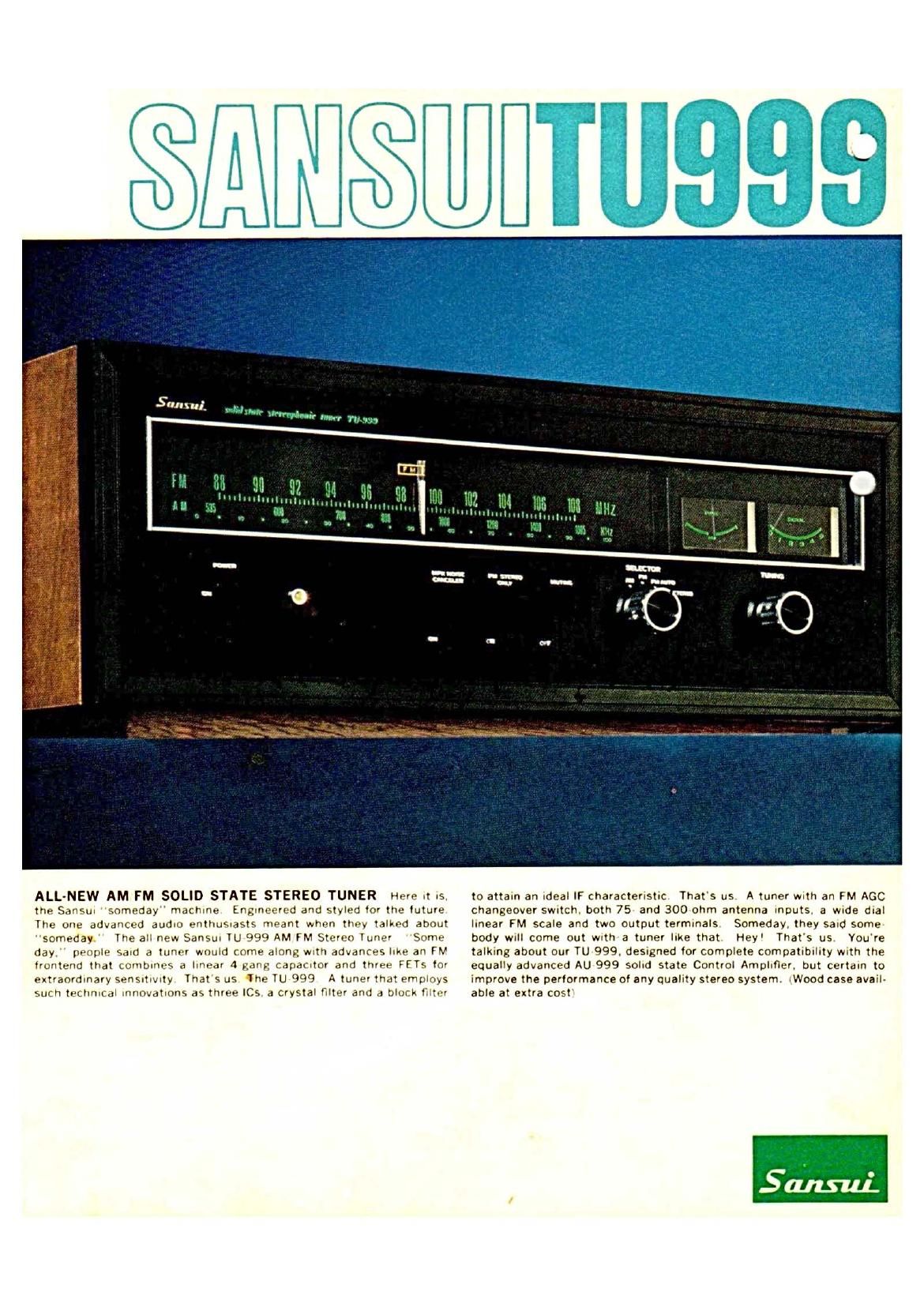
ALL-NEW AM FM SOLID STATE STEREO TUNER Here .1 .s.
the Sansul someday" mach-he Eng-neered and styled tor the future
The one advanced auduo enthus-asts meant when they talked about
"someday The all new SanSu: TU 999 AM FM Stereo Tuner Some
day." people sand a tuner would come along wlth advances I-ke an FM
lrontend that combines a Imear 4 gang capamtor and three FETs tor
extraordinary senSIt-wty Thats us he TU 999 A tuner that employs
such techn-cal mnovatuons as three ICS a crystal filter and a block filter

ll||l|lll|lll'llll!|

let

llllllu

to attain an «deal IF characteristic That's us A tuner with an FM AGC
changeover swrtch. both 75 and 300 ohm antenna Inputs. 3 wade dual
lmear FM scale and two output termmals. Someday. they said some
body wrll come out wrth a tuner like that. Hey' Thats us You're
talking about our TU 999 deSIgned for complete compatlbullty wvth the
equally advanced AU 999 solnd state Control Ampllfler. but certain to
improve the performance of any quality stereo system. lWood case avail-
able at extra cost

Page 2

Tl|999

IM IF Amphliur By adopting three le,
a crystal filter and a block filter, the TU 999
achieves an Ideal IF characteristic far be
yond what is poss:ble through the use of
a Single crystal filter. The result is a great»

ly improved distortion factor. and equally
better stereo separation and phase charac-
teristics at high frequencies when the tuner
is receivmg stereo Signals

Anvmic-d I'M I . lll"'id Three low neise
MOS FETs are employed for the two RF
stages and the mixer stage. Combined
with a 4 gang variable capaCItor, they en
sure an exceptional sensitivity figure of
l8iiV UHF). and result in a substantially
improved intermodulation distortion factor
as well as enhanced image and SN ratios.
Exceptionally steady hi fi FM stereo recep
tion even in remote areas is now a reality

0.:iihli- Mi-ti rs Inform.

limit it A pair
of meters aid in achieving preciSion tuning
of FM signals with the TU-999. One indi
cates the strength of the signal being tuned
in, the other facilitates center oftherchan-
nel tuning Together they make tuning more
preCise and more distortion free than ever
before

It; qui- 'll(" 1 I Hi~i1.i- IL [)lblilllwll
The TU 999 adopts an LC type filter for the
multiplex carrier leak filter Endowed With
a sharp cutofi characteristic. this filter com-
pletely prevents carrier leakage so that heat
interference and consequent intermodula
tion distortion have been drastically re-
duced

u-

vi r Swi'il

fM Affilit Ii 13w This feature
permits precise control of the FM AGC
circuit for LOCAL, NORMAL and DISTANT
stations to ensure quality, distortion free
FM reception regardless of how close or how

far away broadcasting stations might be.
It also results in a very Significant improve:
ment in the S N ratio when tuning to dis
tant Signals

FM AGC
DIST NORM LOC

Slr'l'" ('7' Iv 5am ii In addition to the
Mode Selector which governs the ch0ice of
AM, FM, FM AUTO and FM STEREO modes,
a Stereo Only Switch has been provided to
permit tuning in FM stereo broadcasts ex
clusively.

wldt()l.1ld.Ll*Mll'4t'.l7 Stiilr The TU.
999 features a horizontal wide dial and a
frequency linear dial scale for the FM band
where frequencies Can be read out in steps
of 200kHzt Tuning is easier and more pre-
cise.

1w (liittii.! 7: VII - One Of the TU
999's outputs is an amplifier output termir
nal for controlling output level between 0
and 2 volts With a Level Adjustor The
other is a recording output terminal whose
level IS fixed at O 4 volts

{Ut'l «mil/"a Anti y~l:tw7|lll ,
Of the TU 9995 two FM antenna input
terminals, one is for a 300 balanced an
tenna while the other accepts a 75 un
balanced coaxial cable antenna suitable for
long-distance reception or for reception in
nOISe filled areas

Mnr ,;_ ii-.l Attyislv This speCIal ad-
justor has been provided to control the
working level of the muting Circuit It per
mits optimum muting action in different
areas

ii,ii 5:.» AM ii .

A large ferrite bar antenna and a 3 gang
variable capaCItor are employed in the AM
tuner section to achieve a high senSitivity
figure. The section also has exceptional
capability in squelching interference,

Other Features:

FM Stereo Indicator

AMFM Selector Indicator

FM MPX Neise Canceler

FM Muting Switch

Automatic FM Stereo Mono SWitching
SOIus75/is FM Deemphasis Changeover
SWItch

Illuminating Dial With Self lighting Pomter

NV! (,if ILATIUN)

i .. x i. . V
TUNING RANGE: 887108MH2
SENSITIVITY:

(20:18 quletlngl 1.4iiv

(INF) lBuV

TOTAL HARMONIC DISTORTION:

less than 0 3% niiinn

less than 0 5% stereo
SIGNAL TO NOISE RATIO: better than 65dB
SELECTIVITV: better than 70dB
CAPTURE RATIO (IMF): I SdB
IMAGE FREQUENCY REJECTION:

better than 90dB
IF REJECTION: better than IOOdB
SPURIOUS RESPONSE REJECTION:
better than lOOdB
better than 38:18 at
400M:
SPURIOUS RADIATION: less than 34dB
ANTENNA INPUT IMPEDANCE:

30012 balancedt

75m unbalanced

STEREO SEPARATION:

ii'. Mil Ill/4

TUNING RANGE: 535 1,605kH1
SENSITIVITY:
ibarantonna tso~v at LOOOkHz

'IHFl 30va at LOOOkHl
IMAGE FREQUENCY REJECTION:

better than 80dB at
1,000kHz

better than 20:18 at
LOOOKHI

SELECTIVITV:

RATED OUTPUT VOLTAGE 0 2V

TAPE REG 0 av
FM MUTING LEVEL

OUTPUT LEVEL

FWI MUTING ON on

MPX NOISE CANCELER OFF 'ON

FM AGC DISTANT ,/ NORMAL/
LOCAL
SELECTOR AM FM MONO . FM

AUTO , FM STEREO

~" l .>'t.

TranSistors 32. FET73. IC73. Zerier Diodes 2,
l)t0d95"22
POWER VOLTAGE 100.110.117.127220
230 240 and 250V.
50 60H1
l9VA
155mm 6 .' H - 435mm
17 L'W: 316mm [2 'D
101kg 22 lbs.

POWER CONSUMPTION