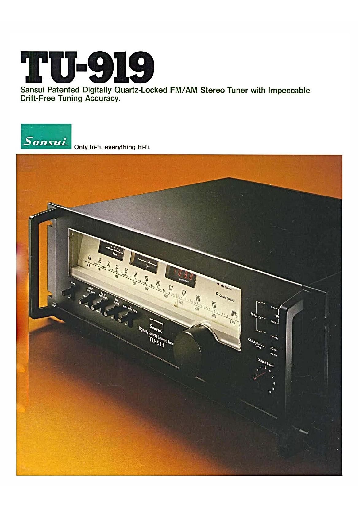
Sansui TU 919 Brochure

This is the 6 pages manual for Sansui TU 919 Brochure.
Read or download the pdf for free. If you want to contribute, please mail your pdfs to info@audioservicemanuals.com.

Page: 1 / 6
left right
Sansui TU 919 Brochure

Extracted text from Sansui TU 919 Brochure (Ocr-read)


Page 1

Til-919

Sansui Patented Digitally Quartz-Locked FM/AM Stereo Tuner with lmpeccable
Drift-Free Tuning Accuracy.

5 Only hi-fi, everything hi-fi.

Page 2

DRIFT NO MORE

When you build a tuner as fine as the top-of-the-line Sansui TU<919. the last
thing you can afford is to let tuning drift endanger performance. This is why
every single precaution necessary to improve this tuner's accuraCy is built in.
and why we've eliminated drift entirely with a Digitally Quartz-Locked system
that was perfected-and then some-in Sansui laboratories.

Quartz, as you know. is nothing new. What is new is the
way Sansui continues to use it for dependability. Since a sliver of quartz
crystal (similar to that used in fine timepieces and turntables. etc.) can be
energized to emit a reference frequency of extremely high regularity. there's
nothing quite like it for tuning accuracy. In the TU-919, the Sansui engineers
have combined it with digital control for more than tuning convenience and
cosmetics. Once you quartz-tune your station. the backup circuitry we've
employed for the digital frequency control keeps it locked.

This unique and highly effective Sansui system is just one
of the reasons why the TU-919 is a desirable and dependable precision
instrument. included is a Darlington-connected differential lC in the IF. select-
able bandwidth circuitry. and other key developments which ensure both
better tuning accuracy and faithful audio reproduction than any comparably-
priced tuner. At Sansui. where it's a// hi-fi. the TU-919 continues the super-
lative tradition of high performance.

BLOCK DIAGRAM OF SANSUI DIGITALLY QUARTZ-LOCKED TUNING

Digital Display | : I
?

h 'The detector drops hundredth: (.01) of 5 or below and round:
off hundredth: of 6 or above to the next tenth.

1. The frequency divider (1) receives the FM frequency. generated by frequency with the precision on the order of ifoppm (parts per million).
the local oscillator. and reduces it by dividing by a factor of 100 to a low Up to this point. control is made digitally by Sansui'e patented tuner tech-
frequency. nique. Detected devration or error is sent to the D-A converter (4) which.
2. The 6.5536MHz frequency. oscnllated by the quartz-cystai osctllator (8). in turn. converts digital corrective information into control voltage. If

is divided by the frequency divider (9| to obtain a 0.018ec gate time base corrective information is present. voltage la instantly applied to the oscillator.
for frequency counting. This time base is then used to count frequency (7). And if no correction is required. the frequency is then locked. turning
from the local oscillator. the green "LOCKED" indicator on.

3. The detector circuit (3) detects frequency deviation (if any) from a tuned 4. The signal fl then passed to the op amp (5!. then to the low-pass filter (6).

Page 4

l

15 18 ll]

tit

tiltlll

lllti ltlti

vrttimti. it...i| ti
HUI] lfilttl

l t H
t-ltiivlt

Ilt I i I t il-
hill Htlll

-794,

l lkllll

Digitally Quartz Locked Tuner
T U-919

For this reason. you It want to use the WIDE posmon on the IF
bandwtdth selector, When the statton to which you have tuned is
strong enough the results in improved htgh frequency response
are impresswe

On the other hand. weak or distant AM stations
are received more clearly when you use the NARROW posnson.
the Interference caused by stronger stations broadcasting on
adjacent frequencies IS dramatically towered

Sansui Tuning Conveniences.

OFM WIDE/NARROW BANDWIDTH SELECTOR.
tn normal operation you'll use the WIDE mode to maxrrnize
potential sound quality in FM broadcasts which can be received
Without excessive interference. But when reception difficulties
threaten to destroy mumcal quality entirety. sw:tch to NARROW
tn the latter case. the station you want is pulled through the inter
ference. wrth retection and suppressron ratios high. by specrat
CirCuilry tn the IF section,

OFM ADJACENT CHANNEL FILTER
FM stations in urban areas are usually crowded on the dtal erh
as ttttte as 400kHz between them The specrat phaselinear
Adjacent Channel Fitter, plus a phase equalizer. at the detector
output of the TUVQIQ ends the brrdie ROISG (beat n0isei often
heard in tuners with conventional IF fitters

oFM MUTING
Swrtch in the muting to end annoying Inter-station neise as you
tune LOfl Signals are eliminated

. FM Stereo

0 QJIHIW

ttllll

MHZ

KHz

non

Tone -m

Output Level

OCALIBRATION TONE
This SWItch sends at 400Hz test Signal to the tuners Output to
permit you to adtust recording levels on connected decks. etc
OFM AUTO NOISE FlLTER tPat Fend t
FM Signals tooweak for respectable hrfi reproduction in stereo are
processed for more listenabte quality when you use this sw-tch
OSTUDIOVINSPIRED DESIGN eRack-mountable
sizrng tbrackets for ElAstandards 19inch rack included) and
distinctive Sansw matte-black ttnish
OTWIN SIGNAL/TUNE METERS
Responsrve and useful. hard to saturate to indicate false reading.