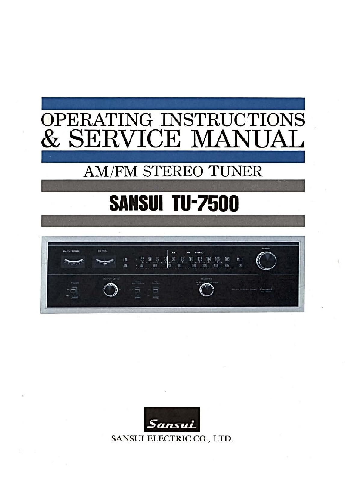
Sansui TU 7500 Service Manual

This is the 25 pages manual for Sansui TU 7500 Service Manual.
Read or download the pdf for free. If you want to contribute, please mail your pdfs to info@audioservicemanuals.com.

Page: 1 / 25
left right
Sansui TU 7500 Service Manual

Extracted text from Sansui TU 7500 Service Manual (Ocr-read)


Page 1

OPERATING INSTRUCTIONS
& SERVICE MANUAL

AM /FM STEREO TUNER
SANSIII TU'7500

SANSUI ELECTRIC CO., LTD.

Page 2

We are grateful for your choice of the TU-7500 FM/AM Stereo
Tuner.

For over a quarter of a century, Sansui has been building hi-fi
audio equipment, and nothing else. Our mission is very old and
at once ever new to us: to bring the reproduced sound closer to
the original.

The TU-7500 now in your hands is one answer from us to this
never-ending quest. It is a product of the cream of sophisticated
modern audio-electronics knowhow, coupled with our long experi-
ence, and as such, we present it to you with our full confidence.
The TU-7500 is a matching tuner for the Sansui AU-75001nte-
grated Amplifier. It features an FM multiplex circuit utilizing
a differential amplifier for outstanding channel separation, dis-
tortion and phase characteristics, the last one being of particular
importance in receiving discrete 4-channel FM broadcasts antici-
pated in the future.

This manual has been prepared to guide you in operating and caring
for the tuner correctly, so that you will get the most out of its
built-in high performance.

May we suggest that you read it once carefully?

CONTENTS

SWITCHES AND CONTROLS ....................................... 3, 4
CONNECTIONS ......................................................... 5, 6
OPERATION ................................................................. 7
SIMPLE MAINTENANCE HINTS ................................. 7, 8
GENERAL TROUBLESHOOTING CHART ........................ 9
SPECIFICATIONS/ACCESSORIES ................................. 10
DISASSEMBLY PROCEDURE ....................................... 11
TEST POINTS ............................................................ 12
SCHEMATIC DIAGRAM .......................................... 13, 14
ALIGNMENT ......................................................... 15, 16
PRINTED CIRCUIT BOARDS AND PARTS LIST ...... 17~24

OTHER PARTS AND THEIR LOCATION ON CHASSIS... 25, 26