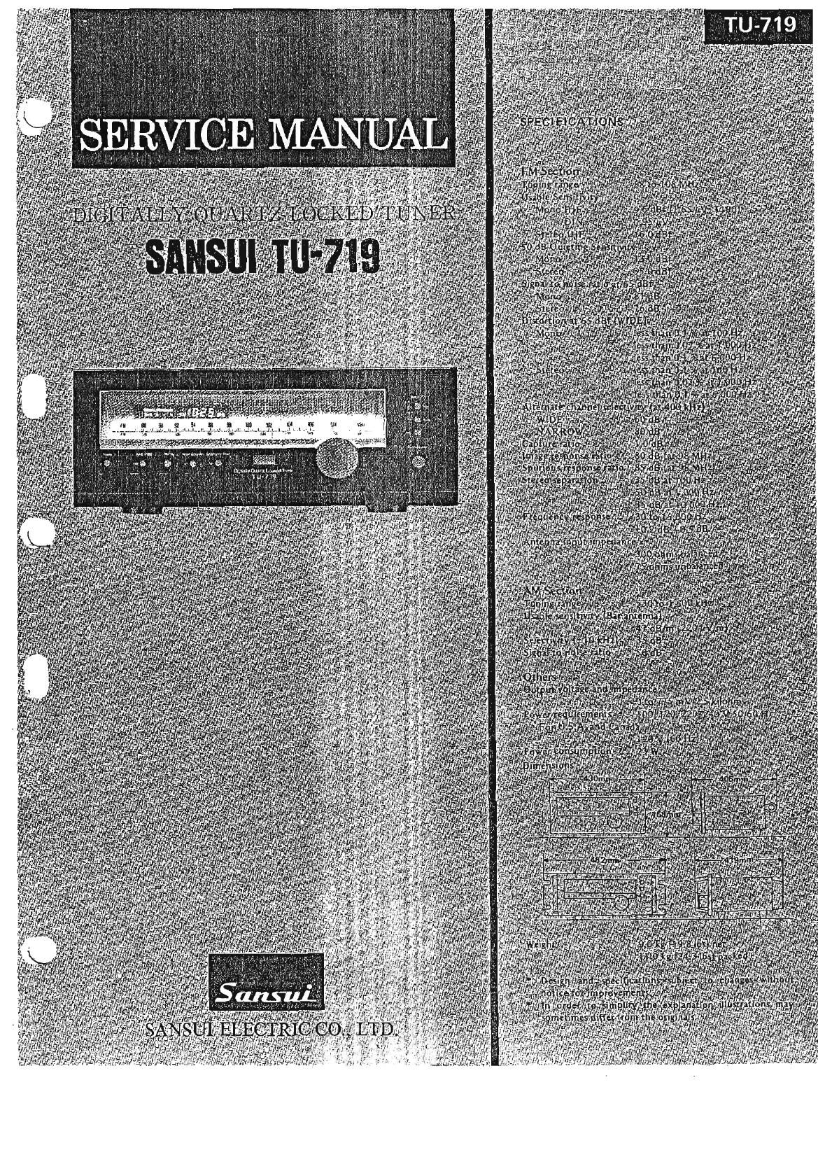
Sansui TU 719 Service Manual

This is the 25 pages manual for Sansui TU 719 Service Manual.
Read or download the pdf for free. If you want to contribute, please mail your pdfs to info@audioservicemanuals.com.

Page: 1 / 25
left right
Sansui TU 719 Service Manual

Extracted text from Sansui TU 719 Service Manual (Ocr-read)


Page 2

[7 - F 0 (KC To; 1 '\¥

rFMFrarIl EndPack lC ranoze IC LAI222 Ic HA-il2
- I TRm CFoI 01 CF03 CF04 02 Wm 03 25
e ' - a 5 To
FM _® W of; DETECTOR °Ei_
i3 3&9 {a a ,3
l _
I
I_ | .
,' "" » . moss l
l ' I
. Fag) .
i i _ mad
l l
L.___ J

Mum;
_ _ - JPE'LCEEEEE BEE)- I Lg
PM ME ' W®Taw
Pie Sonia FM SIGNAL
AM an FM moo mwmc _
(r-3moI ' _

AM SIGNAL +3 mos


TRis
i 1096!: K i '
: -Camu , CosHA'l l223W POST AMP LdI
.; D A Convener g}? 1% 1 -
; 533$ng g a __ g ' F'LL MPX 6 W
_ - -------- PLLO A
t J M lCoaLA-lZMJ T C OELER 5 mos E
a
i c SEPALATION 8.:
DiGiTAL g é AM 16 5050:2977) Ad' VR n:
DISPLAY '3 SELECTOR ' > g
her-d
\ LCD] 4/

2'. OPERATIONS

2-1. Description of HA11223W
(1) Ou'uine (See Figs. 2-1, 22, and 2.3.)

O'The IC HA11223W is a PLL-MPX K: with a low distortion
factor and a high slgnal-to-nolse ratio. This IC performs two
significant functions during stereophonic reception, namely a
beat-reducing function for high frequencies and a pilot-cancelling
function. In this section, a recently developed pilot canceler cir-
cuit is described.

I When decoding composite signals (composed of main signal,
pilot signal, and subsignal), right-side and left-side signal can be
obtained, but the pilot signal is also decoded so that it appears at
output on the right and left channels as shown in Fig. 2-1. These
signals, when amplified by an amplifier, are distorted by the non-
linear part characteristic of the amplifier, resulting in poor tones.
To avoid this. the pilot signals must be removed or cancelled
from the composite signals before the decoder;

Fig. 2-2 shows how the pilot signals are cancelled in the lC
HA11223W.

(2) PilotCancelling Operation (See Figs. 2-1 and 2-3.)

0 in the IC HA11223W, a composite signal (including a pilot
signal) applied to the pin 2 is fed to a PLL and a decoder circuit
through a preamplifier.

The 19 kHz square wave signal generated by the PLL circuit is
advanced in phase by 90 deg against the input pilot signal. This
Square wave signal, after it is output to the pin 9 through a gain
control amplifier (where the gain varies with the pilot signal
level), Is delayed by 90° in phase and converted to a triangle

wave signal by an external integration circuit connected to the
pin 9, then applied to the pilot canceler circuit within it: from
the pin 4. 0n the other hand, the composite signal input to the
decoder circuit is applied to the pilot canceler circuit to at-
tenuate the pilot signal, and fed to a 100% NFB amplifier, and
then output to the pins 5 and 6 as left and right signals through
the switching operation of the decoder.

Fig. 2-1
The Output Waveforms of 19 KHz
Pilot Signal Switched by 38 KHZ

Fig. 2-2

Pilot-Cancelling Operation Waveform

0 wave lormo l I l
l KHz Pilnl sigmi 1 g

l I I :

I : I I

.0le wave lorm o
' without 063150

I
I
: I
I ' i I: I II
IMMWaveien-noll i i I l i
V Pln® ' : i I '
I l I I l |
I l I i
I l 1 I

T4

0 Input wave form 0|

decordar W L