Sansui TA 2050 Owners Manual

This is the 4 pages manual for Sansui TA 2050 Owners Manual.
Read or download the pdf for free. If you want to contribute, please mail your pdfs to info@audioservicemanuals.com.

Page: 1 / 4
left right
Sansui TA 2050 Owners Manual

Extracted text from Sansui TA 2050 Owners Manual (Ocr-read)


Page 1

W

Thank you for selecting the Sansui TA-2050 Stereo Tonearm. As one of the worlds
foremost audio-only specialized manufacturers of quality stereo equipment, Sansui places full
confidence in its quality and assures you that it will provide truly high-fidelity reproduction
of your favorite records. It permits any light trztcking- force cartridge of vour preference
to track the record groove faithfully without the slightest possibility of damaging your

valuable records

It is now up to you to read carefully the instructions given on the following pages to install
it correctly and enjoy its performance potential to the fullest.

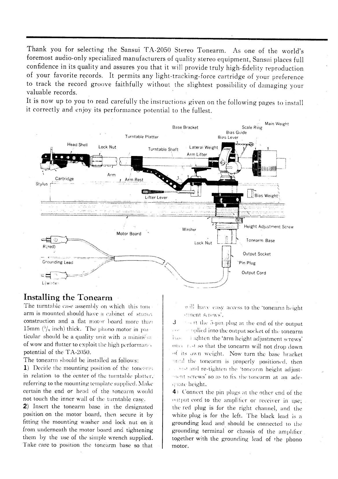
Turntable Platter

Head Shell

Base Bracket

Lock Nut Turntable Shaft

Main Weight
Scale Rang

Bias Guide

8125 Lever


Lateral Weight
Arm Lifter

4

\ Arm ,l
, Cartridge , 1, 7 ,J,,Ar.m.l3§5t
Stylus r; 77 V 7 V "W V

liltllllllll

___l

=1 ~" "

L(w.:".e1

Installing the Tonearm

The turntable (use assembly on which this lUllt
arm is mounted should have a cabinet of sttirti'.
construction and a flat utotoi' board more than
15mm ("/.1 inch) thick. The phono motor in pm
ticular should be a quality unit with :1 111ini11'1711:
of wow and flutter to exploitt no high perforinzmei
potential of the A- 2050.

The tonezirui should be installed as follows:

1) Decide the mounting position of the lOlltI'l'll
in relation to the center of the turntable pluttt-r.
referring to the mountinpr template supplied. Make
certain the end or head of the tonczu'm would
not touch the inner wall of the turntable case.
2) Insert the tonearm base in the designated
position on the motor board. then secure it by
fitting the mounting washer and lock nut on it
from underneath the motor board and tightening
them by the use of the simple wrench supplied.
Take care to position the toneiirm base so that

' Tonearm Base
Lock Nut

Output Socket
\Pin Plug

Output Cord

haw 1-;1s_\1 access to the 'toneurm hviglit
uncut st 11- s.

.3 1, it 1111- Spin plug at the end of the output

. .1. 'tl)ll('(l into the output socket of tht- tonearm

it...» l iuhtcn the artn height adjustment screws'
mu. :-.4 so that the tonearm will not drop down
at its oun weight. Now turn the base bracket
'll"ll the tonezirtn is properly positioned, then
Wu and re-tightcn the tonczirm height adjust~
it'lll st'rcws' so as to {ix 1hr- toncarm at an ade-
«liillt' height.
4) Connect the pin plugs at the other end of the
1»1ltl)tttt()l(l to the amplifier or receiver in use;
the red plug is for the right channel, and the
white plug is for the left. The black lead is :1
grounding lead and should be connected to the
grounding terminal or chassis of the. am} zlilier
together with the groundingl e 1d of the phono
motor.

Page 2

Installing a Cartridge

1) The tonearm head shell is already proyided
with loads, and you only need insert the tips of
these leads into the connecting pins of the car-
tridge you wish to use. These leads are color~coded
according to the MA Standard: the green one is
for the minus of the right channel, the. red one
for the plus of the same, the lJlLlL OIlL' for the
minus of the left channel, and the white one for
the plus of the same. The lead tips are designed
for-Sansui cartridges, and may he too thick or
thin for certain cartridges of other makes as the
thickness of the connecting pins of cartridges is
not standardized. Should you face this difficulty,
replace the lead tips with the ones supplied with
your cartridge.

Black


Bolts T . " t _ *- ~Blue ii
. * I w-
Leads » * s . ._ *wtl !-
. ix
' 2' -~ - Washers I,
K :
s6.
i
l HeadCorinCertlml 1 a °Red
- « RediRignt "tannel - r ,
:64" (. Black Green Right Channel Green
Willie? Lett Channel .
BluewLett Channel
To
l.- wmte , YR Red
s
Tips \ H \.
i ll ll
. l i. K .t i ,
; t ' Cartridge /
Pins. \ g . .:
Blue: Green
. a ,
t
as

Nuts

2) Once the cartridge is installed in the hcad
shell. insert the shell into the tip of the tonearni
and secure it liy turning the lock nut Cl()(l\'\\l>t
and tightcningfir it. Pay attcntion throughout tin

)rocedure not to a ) )ly unnecessary )ressurc (r;
. . l

the tonearm hase.

Head Shell

, Lock Nut

Cartridge

3) Loosen the cartridge retaining screw on the
head shell, slide thc cartridge back or forth to
adjust the Oyerhang. This adjustment is more

easily accomplished by following the mounting

MM

template supplied. The optimum overhang for the
'l;\-2()3l) is l51filil(" . inches). Once the cartridge
is correctly positioned. tighten tht- tartridge re-
taining screw.

Adjusting the Horizontal Balance
and Tracking Force

1) First adlust the horizontal halancc ol the

tonearnt. lnsert the main weight from the rear
01 the tonearm, placing it so that the side with
the tracking force scale laces thc front of the
tonearm. The weight moves very smoothly when
rotated in the direction of the arrow. Now halance
the tonearni horizontally liy turnintr the entire
main weight back or forth.

This is

2) Next, adjust the
achieved by turning only the tracking force scale

tracking force.

ring, while holding the main weight itself still,
until the 0" mark on the scale comes to the
center line on the. tonearm shaft.