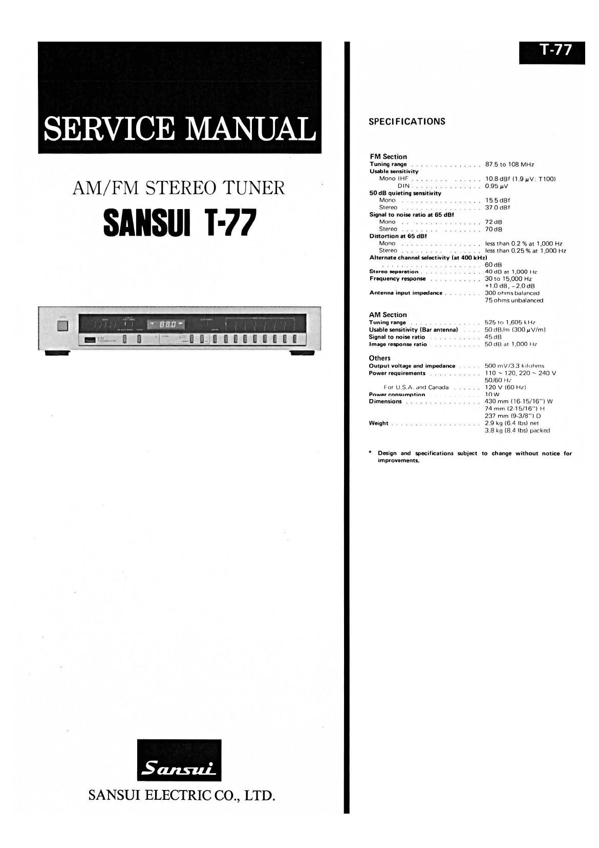
Sansui T77 Service Manual

This is the 14 pages manual for Sansui T77 Service Manual.
Read or download the pdf for free. If you want to contribute, please mail your pdfs to info@audioservicemanuals.com.

Page: 1 / 14
left right
Sansui T77 Service Manual

Extracted text from Sansui T77 Service Manual (Ocr-read)


Page 2

<> BLOCK DIAGRAM


\
( _ _ _ .EF_M_ :@ ___________ _ IF Amp 8: FM Detector MPX Decoder
, dFTI dOl l ace do. dCFz "V
I dL' flL2 0L6 I 7 L'Ch OUT
I I /-{>- \\ / -. dlCi LAI23I s 2 dlCz )JFCIIGI aOzL
FM 3000 I do I V _® 60»
2 I I I0 5
' A I c 3 2 Q CIR-ch OUT
I T: m dFTz l - FM zlqndl . dTZ d02n do
I .33 3 .L a") ' an
L :3. I): III (M S I E:
--L - '- uiing iqno '
FM Section
ecFI Kw Mule Signal» AM Signal»
AMC BAR ANT 9T.
3
I: H a - FM Signcl >
P 23 g 6"? 'SIGNAL LED DRIVE
,» cifl EICI HAll97 iFIipV-TF@ 2 3
5 «TI .5 ,3 9 FM LutouDMOM-fi) Cs talFM) nICI LBI4I6
3 ii AM SIGN i 2 LAM i? Kim NANDM I; Is 2
U . c , ,
4f i \AM IF Signal ; ______ LI AUTO/ .1 15.9w 2) UM fl
'3 cI , 77
§ :ojI Loop Filter 033mb If: 34 Egg
____________ G
E E): I- {01 1I 2M [Fl-mil (AMAulo-SIODSanaI\ ® ® $ $ $
' NOR-3 ' 7
2 I
(NC I , ,i ,_
7 no toeiozp : 'CF' Eco T0 7-SEGMENT.
FPre-Scaler _ _ IOEITJQ_ EECQUnBck . @(XEEBL ._l
I- -'1 Unloét oflgjgggHz [MUTE '0'? E3): nOIs nOn nOIa nOIs n02o anI ma
. . . an
m 69 m» ®®®o®®®
7 D :1 C Is
aABCD 2
I J i 353 I: aia
_ ' .A FIP DRIVE
@ffifl - - - 7 nOs n05 n07 n09
®®®®®®®® e W @®®®
1-K- VooIQVl (TI,T2,T3,T¢>
,: [I v , 5 __ ) @nOz
g .. _ _ an a ; (passer STATION) DOWN LP
335:: SEC; §§§§§ _ ("- "0s cmo obcdefg
a 9 > > n6fl6fl6 6fl6n6n66fl 66 r_«.fl66' 1., 6 , 8
a " 9'2" 7 7 VI? ? ? tut tel? c: I ®"° w MEMORY I l-II_ I
is we; mama; E m I HI I IL! Itll?
- fl 1 '0 N " '- - " " - ' _ _ - l-I
AM/FM Select I E i g 00 - t0u®rois® nOa® E
l I ma
route-stop Signal) ® ® 51 Lamp DRIVER
(03
IS: é
IM/FM (TIITZ)
L
1. OPERATION
1-1. General 1-2. Operation of quartz PLL synthesizer circuit
The main functions of the Quartz Synthesizer Tuner T-77 will be Fig-1'1 PLL Synthesizer bIOCk diagram
described below: RF
1 M l . f h 875 »meouuz(mi M e, IoliIEzILMI
) anua tuning 0 one step/one pus . Powwow Ix 460kHz(AM)
If UP or DOWN key switch is pushed once lightly, the receive fre- f
quency (every frequency displayed on the indicator tubes) changes Egg * W v ignorant/{fling
by one step (100 kHz in FM; 1 kHz in AM). ass-"W
2) Fast forwarding tuning E G-IIUIIZ
. . . . A l D -u , ,7 7v
While UP or DOWN key swuch is kept pushed slightly, the receive g 5 5 1 LRefiirfncelreq,
- I T: - ____________________
frequency continues to change. E g f I I 12??sz 1,
. . E . k
3) Automatic search tuning T § : 5:;ser5nc1a $223522: / z I
If UP or DOWN key switch is pushed once deeply, the receive fre- g 3:? : mm a" :
quency continues to change and stops when it reaches a frequency 1 :
of the next broadcasting station. Prescaler : P'Ofi'amwjfie 60"6' ~- Phase :
4) Memory write and memory read 'F MW" " mm / I IZSSEZéAZEEml l25kHZ(FM) :2?" I LPF
By pushing MEMORY and STATION key switches, it is possible to I : Nzntlonm) WW I
store the receive frequencies of six FM/AM stations. And also, by / I N'Mwuw J'
- . . . , L ______________________
pushing one of STATION key swnches once, it IS pOSSlbIe to select 12275-145375MHzirM) iPresetlnDUI
. . . 985 ~2oesmz(w) I "=3751°3°(FM)
any desired station automatically. 1n=525 ~1605(AM)
. . . . K t b d
5) Digital display of receive frequency mfiflnfilliméwcmo -- (5392:3303: :ar'eceive
The receive frequency is displayed digitally by using fluorescent "mum
indicator tubes. Fig. 1-1 shows a PLL circuit for stabilizing the local oscillator fre-
The Quartz Synthesizer Tuner T-77 comprises a PLL synthesizer quencies.

circuit (TC 9123P) for mainly stabilizing the local oscillator fre-
quencies, a synthesizer control circuit (TC 9124AP), a digital display
circuit (TC 502QBP) for displaying receive frequencies, and a muting
control circuit.

The local oscillator frequency fed from a VCO local oscillator is
divided by a Pre-Scaler section, and further divided by a program-
mable counter section (a counter by which a divide ratio N can be
predetermined freely by presetting it from outside) into l/N.

Page 6

2) When AM is received (See Fig. 1-8)

In the case where AM is received in the automatic search tuning, the
muting operates in the same way as in the case where FM is re-
ceived.

If the search operation begins, the AM/IF amplifier (fog and f0)
comes into operation. The output of the AM/IF amplifier is con-
nected to Pin 8 of NOR-3 and is usually kept at H level. Also, since
Pin 5 of NOR-2 is at H level in AM, Pin I of NOR-I is fixed at L
level. Since Pin 2 of NOR~1 is at H level during scanning operation,
Pin 9 of NOR-3 is at L level.

If a frequency of a broadcasting station is received, the AM wave is
amplified by ng and le3 and is then applied to Pin 8 of NOR-3.
As a result, when it reaches a threshold level of Pin 8 of NOR-3,
Pin 10 changes as shown in Fig. l-9 and this output turnsz ON
through a narrow.band ceramic filter.

This narrow-band ceramic filter is used to prevent error operation
due to noise in the automatic search. As a result, Pin 12 of NOR-4
changes to L level, At this time, if the signal indicator level exceeds
two, f0, is turned ON to change Pin 13 of NOR-4 to L level and
Pin I I to H level. The signal of Pin 11 is an AUTO/STOP control
signal for the control IC of TC 9124AP; therefore, the automatic
searCh operation stops. As a result, the pulse generated at Pin LD-
out of the PLL synthesizer IC TC 9123p is stopped to change Pin
2 of NOR-I to L level and Pin 3 to H level, and thus the muting
operation is released. In the case of manual tuning, the muting
operates for a moment when the UP/DOWN key switch is depressed,
in the same way as in the case of the manual tuning in FM MONO,

Fig. 1-8 AM Muting control circuit

m Tuna-r IC

'C' "197 Meier OUT

I5'-*

9
IF OUT

lama Lock~®ms
Unlock "I, 15
L0 OUT

IE2 rcstzsP

IOI2

IOn

" '-" LCHOv'
-6;

i

-OP CH OUT
60:»!

Till

0C 3 TCSIZIIP

A- STOP
I12

gontrul '0
Fig. 1-9

LBMIG
a

' | l
.-

NOR3 Pin 8
Input Signal

NOR 3 Pm 10
Output Signal

H. Level

L Level

2. INTERIOR BLOCK DIAGRAM OF IC

4. HA1197 (AM tuner IC)

1. uPC 1161 (MPX Decorder IC)

llfil I15 IUI ll3l IIZI llll IIOI 9|
PLOT smite
vco, ms: LOCK mm: 5 Tc
76 DETECTOR 0:1:ch LYWBMVER
i l I *
si-msw 76m: to m: to saw 10
P VLO STOP 38m I9lflz lkiz
94 mm owner: cum:
I L-Ol
[-i- I I I" P051 Aw
STEREO
PRU"? "FM Whoa H.
I__l 905nm
-1 l-""-
Ill [2II3II4II5116II7II8I

2. LA-123'I (IF amp & FM detector IC)
l1 s 9 l0

I Voltage Regulator I Quadrature V
LImItIer
IF Amp/Liming: f fife/(Tune _7
1-*1st 2nd am am 5th 6th t Quadrature Um
I #- Detector
3_ Audio 6
Amp
I Level Level Level imer- Level IX: Level _ _ _ _
4 De! Der, Der, ter Bet Bet mm __5
Mute
lF Amp Signal Meter Mute
Mite Drive Drive fl
. l l
15 13 16 12 H
3. MSM4001RS (NOR1 ~ 4)
VDD

14 13 II 10 9 8
I 112 l I

w <93

II

SUB

IFA-S

AGC DRlV

é)

" SM WIVI

5. LB-1416 (Signal LED drive IC)

Vcc Vref R02
8 5 4

6. MSM4011 RS (NAND 1 ~ 4)

VDD

O 8
I I

no

141312111
I I I I

D

GND