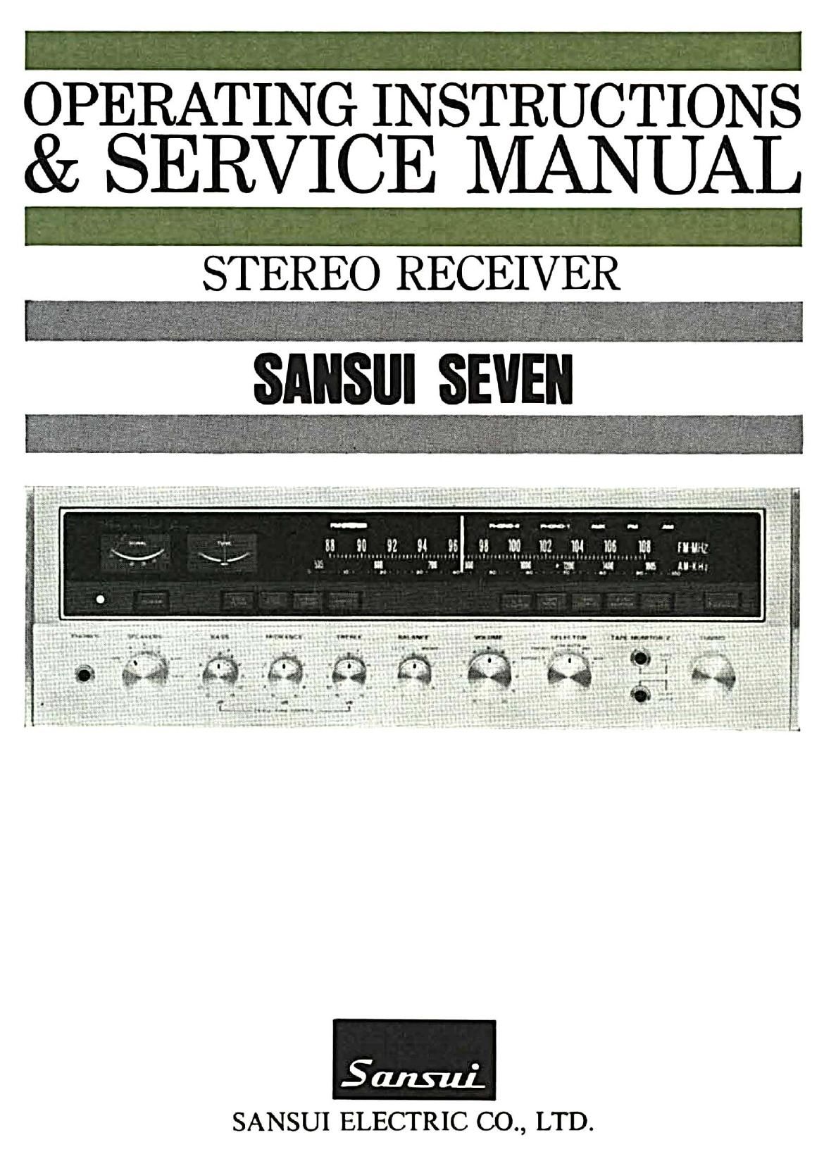
Sansui Seven Service Manual

This is the 39 pages manual for Sansui Seven Service Manual.
Read or download the pdf for free. If you want to contribute, please mail your pdfs to info@audioservicemanuals.com.

Page: 1 / 39
left right
Sansui Seven Service Manual

Extracted text from Sansui Seven Service Manual (Ocr-read)


Page 2

Congratulations on joining the thousands of proud, satisfied owners
of quality stereo components from Sansui, Japan's foremost audio-
only specialist.

In many ways, the SEVEN is a culmination of our long experience
and arduous research in the design and manufacture of quality audio-
only equipment.

Its tuner section combines an FET~equipped super sensitive FM
frontend and an IC-equipped FM 1F amplifier which ensures outstand-
ing FM selectivity and superb tone quality.

Its amplifier section is a ISO-watt masterpiece designed, tested and
proven to bring out every subtle shade of the original sound, regard.
less of the program source, free from distortion.

Over-all, the receiver is equipped with practically all the switches,
controls, inputs and outputs that you would ever need to enjoy todays
most advanced hi-fi sound reproduction.

This manual has been prepared to guide you in operating and caring
for the receiver correctly, so that you will get the most out of its
built-in high performance and exceptional versatility. May we sug-
gest that you read it once carefully?

CONTENTS

SWITCHES AND CONTROLS ....................................... 3, 4, 5
CONNECTIONS ......................................................... 6, 7, 8
OPERATIONS .................................................................. 9
4-CHANNEL STEREO SYSTEM ....................................... 10
NOISE REDUCTION SYSTEM .......................................... 11
SIMPLE MAINTENANCE HINTS .................................... 12
SIMPLE MAINTENANCE HINTS/ACCESSORIES ............ 13, 14
GENERAL TROUBLESHOOTING CHART ..................... 15, 16
SPECIFICATIONS ......................................................... 17
DISASSEMBLY PROCEDURE .......................................... 18
TEST POINTS ............................................................... 19
SCHEMATIC DIAGRAM OF AMPLIFIER SECTION ...... 20, 21
SCHEMATIC DIAGRAM OF TUNER SECTION ............... 22, 23
ALIGNMENT ...................................................... 24, 25, 26
PRINTED CIRCUIT BOARDS AND PARTS LIST ............ 27~39

OTHER PARTS AND THEIR LOCATION ON CHASSIS... 40~42