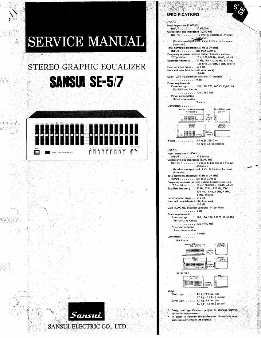
Sansui SE 5 SE 7 Service Manual

This is the 8 pages manual for Sansui SE 5 SE 7 Service Manual.
Read or download the pdf for free. If you want to contribute, please mail your pdfs to info@audioservicemanuals.com.

Page: 1 / 8
left right
Sansui SE 5 SE 7 Service Manual

Extracted text from Sansui SE 5 SE 7 Service Manual (Ocr-read)


Page 2

l
I
l

1. BLOCK DIAGR M

Sourcee T T g r r
9 a a A A
l-REC (c3 3 3. g V
TLAPE-1 0 E0 amp
PLAVC Q m % Flat amp
I I C
[-REC @- t. u. - -4vv1
TAPE-2 " ll -l
LPLAV@- I
.
.
. l
I .
. .
. .
I I
I I
I |
I |
l v '
I l
i '.
l i
.
I lx10 55-7
I Ixs se-s
L J

Flat amp

.

Ion/2 :l- RELAY 3

' OUT PUT
pnorscron
CIRCUIT

2. OPERATION

2-1. Outline (See block diagram.)

The graphic equalizers, Models SE-S and SE-7, consist of a plurality
of resonance circuits (8 units for SE-S, 10 units for SE-7) using a
semiconductor inductor, an EQamplifier using the resonance circuit,
and flat amplifiers.

2-2. Basic Operation of Resonance Circuit

and OP Amp.(0perational Amplifier)
The resonance circuit (Fig. 24) is built with an 0P amp, resistors,
and capacitors, having an equivalent circuit as shown in Fig. 2-2.
It is customary that an OP amp in any circuit is handled as an ideal
one for convenience. In this case, the 0P ampmeets the following
requirements: 7

1. Voltage gain : Infinity
2. Band width : Infinity
3. Input impedance Zin : Infinity
4. Offset, Drift : Zero
5. Output impedance Zout : Zero
6. Common mode rejection ratio : Infinity

Thus, when a signal voltage is applied to the inversion input terminal
of the OP amp as shown in Fig. 2-3, current flows through the resis-
tors RD and Rf, but none flows into the inversion input terminal
because the input impedance of ideal 0P amp is infinity. The volt-
age at inversion input is 0V because the non-inversion terminal is
grounded and input difference voltage (Vd) between the two input
terminals of 0? amp is always 0V (since the inversion input is al-
ways at the same potential as the non~inversion input, the inversion
input is said to be at virtual ground.)
Applying Ohms law to the above, the voltages Va and Vl are:

v0 : 7|; -x Rf

V, II x RD

Fig. 2-1 Resonance Circuit

Fig. 2-2 Precise Equivalent Circuit

CZ

R1

RI

Le