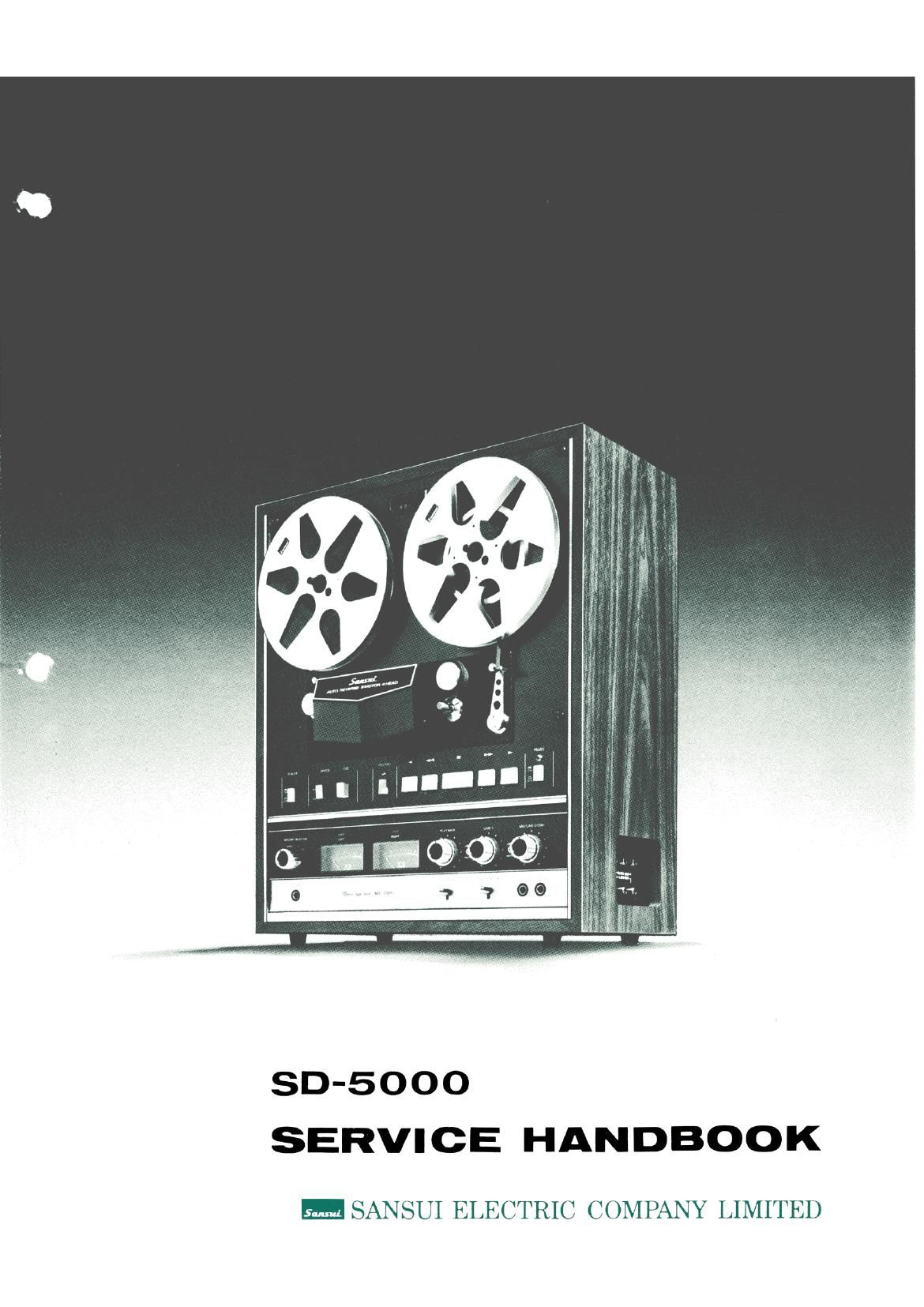
Sansui SD 5000 Service Manual

This is the 57 pages manual for Sansui SD 5000 Service Manual.
Read or download the pdf for free. If you want to contribute, please mail your pdfs to info@audioservicemanuals.com.

Page: 1 / 57
left right
Sansui SD 5000 Service Manual

Extracted text from Sansui SD 5000 Service Manual (Ocr-read)


Page 1

SD-SOOO
SERVICE HANDBOOK

SANSUI ELECTRIC COMPANY LIMITED

Page 2

- 30.75000; -

This handbook is designed for service engineers to repair, adjust, maintain and order the
replacement parts of the SD-5000 correctly. »
When ordering the parts, use the stock number and parts name specifically referring to the
Exploded Views and Parts Locations.

For general usage and maintenance of the unit, please refer to the Operating Instructions
which is on file at the end of this handbook.

Page 14

3-2.

3-2-1.

1)

2)
3)

4)

1)

2)
3)

4)

3-2-2.

®

1)

Reel Motor Torque Adjustment
(See Figs. 3-2 and 3-3)
Tape speed should be 19 cm/sec (71/2 ips)

Turn on the shut-off switch linked with the
tension arm.

Set the reel hub and spring scale as shown in
Fig. 3-2.

Back-Tension Torque Adjustment

Left Back-Tension Torque Adjustment

Place the reel and spring scale on the left reel
table.

Push the FORWARD button V.

Pull the spring scale in the direction of A at a
constant speed (tape speed).

Adjust a slider band 3 of the left torque adjusting
resistor R7 02 (shown in Fig. 3-3) for a reading
of 70 g.

Right Back-Tension Torque Adjustment

Place the reel and spring scale on the right reel
table.

Push the REVERSE button 4.

Pull the spring scale in the direction of D at a
constant speed (tape speed).

Adjustaslider band 6 of the right torque adjust-
ing resistor R703 (shown in Fig. 3-3) for a
spring scale reading of 70 g.

Take-up Torque Adjustment

Left Take-up Torque Adjustment

Place the reel and spring scale on the left reel
table.

2)
3)

4)

1)

2)
3)

Push the REVERSE button 4.

The spring scale pulled in the direction of B at
a constant speed (tape speed).

Adjust a slider band 2 of the left torque
adjusting resistor R702 (shown in Fig. 3-3) for
a spring scale reading of 90 g.

Right Take-up Torque Adjustment

Place the reel and spring scale on the right reel
table.

Push the FORWARD button b.

The spring scale pulled in the direction of C at a
constant speed (tape speed).

Adjusta slider band 7 of the right torque adjust-
ing resistor R703 (shown in Fig. 3-3) for a
spring scale reading of 70g.

3-3. Reel Motor Torque Adjustment in

1)

2)

3)

Rewind Mode (See Figs. 3-2 and 3-3)

Set the SHUT-OFF switch linked to the right
tension arm to ON position.

Place the reel and spring scale on the right reel
table as shown in Fig. 3-2.

Push the REWIND button 41, and pull the
spring scale at a constant speed (tape speed) in
the direction of D.

Adjust the slider band 10 of torque adjusting
resistor R701 (shown in Fig. 3-3) for a spring
scale reading of 20 g.

After the adjustments, run the tape several times
both in FAST FORWARD and REWIND modes,
and check if tape running starts quickly and
smoothly.

Page 41

Resistor: Carbon Resistor ...... C. Resistor

Capacitor Electrolytic Capacitor. . . El. Capacitor -
30-5000 5

Schematic Diagram

TR rm TR/oa 7;? 705
RL101 28C87| RF 23C458LG B,C 23C458 B,C

§<

0109 Cm

25V 4.7525


: 3:
Q fimsgo/r 1
gs s
:: , g {8
c2 _ c
R, 7 550K WA 9
mm Any4.7/< 3mm, VR,
C11347mP(.5'% J 10m) 20%?)

0102
R104 CT
I
g; (3104
(k

5)

G ' | l l I A

Parts List
Parts No. Stock No. Description Parts No. Stock No. Description

2250290 Equalizer Circuit Board G-1111A C107 0513100 10): 25 V El. Capacitor
R101 0101224 220 kg %W C. Resistor C108 0513100 1OMF 25 V El. Capacitor
R102 0101224 220 kg /aW C. Resistor ' C109 0513479 4.7 HF 25 V El. Capacitor
R103 0101152 1.5 kfl /4W C. Resistor C110 0513479 4.7 [.1F 25 V El. Capacitor
R104 0101152 1.5 kg '/4W C. Resistor C111 0513479 4.7 [JF 25 V El. Capacitor
R105 0101684 680 kg /4W C. Resistor C112 0513479 4.7 #F 25 V El. Capacitor
R106 0101684 680 k9 %W C. Resistor C113 0600476 4700 pF (5%) 50 V
R107 0101224 220 kg AW C. Resistor Mylar Capacitor
R108 0101224 220 k9. AW C. Resistor C114 0600476 4700 pF (5%) 50 V
R109 0101223 22 k9 AW C. Resistor Mylar Capacitor
R110 0101223 22 k9 1/4W C. Resistor C115 0601106 0.001 [1F 50 V Mylar Capacitor
R111 0101221 220 9 AW C. Resistor
R112 0101221 220 9 1/-W C. Resistor TR101 0305475 280871R (F) Transistor
R113 0101152 1.5 kg AW C. Resistor TR 1 02 0305475 230871 R (F) Transistor
R114 0101152 1.5 kg AW C. Resistor TR103 0305310, 1 23C458LG (B, C) Transistor
R115 0101682 6.8 kQ AW C. Resistor TR104 0305310, 1 2SC458LG (B, C) Transistor
R116 0101682 6-3 k9 VnW C. Resistor TR 105 0305111, 2 280458 (B, C) Transistor
R117 0101564 560 kg %W C, Resistor TR106 0305111, 2 280458 (B, C) Transistor
R118 0101564 560 kg AW C. Resistor
R119 0101472 4.7 kg %W C. Resistor VR101 1032102 10 k9 (B) Semi-variable Resistor
R120 0101472 4.7 kg /-W C. Resistor VR 102 1032102 10 kg (B) Semi-variable Resistor

VR103 1032122 20 k9 (B) Semi-variable Resistor

C101 0572159 1.5 #F 16 V Tantalum Capacitor VR104 1032122 20 k!) (B) Semi»variable Resistor
C102 0572159 15 11F 16 V Tantalum Capacitor
C103 0660101 100 pF 50 V Ceramic Capacitor RL101 1150180 AE3122-70 DC30 V Relay
C104 0660101 100 pF 50 V Ceramic Capacitor
C105 0660680 68 pF 50 V Ceramic Capacitor P101 2410430 Mini 0106 0660680 68 pF 50 V Ceramic Capacitor P102 2410430 Mini-Connector (6 P)

Page 52

80-5000

Symptom
7. REWIND inoperative

7-1. No tape movement in REWIND - 26)

_ 27)

- 28)

8. AUTO-REVERSE play inoperative

8-1. AUTO-REVERSE play inoperative - 29)

-~ 30)

10-2. Troubleshooting on Electrical Section

1. Power supply troubles

1-1. No power supply to electrical section - 1)

2. Playback system troubles

2-1. Output 800 mV absent at LINE OUT (HIGH)

10-4

Check Point

Reel brakes not releasing

Left reel motor not rotating

Left and right reel motors not rotating

RE VERSE play inoperative

RE VERSE playback inoperative

Correct voltage supplied to each
terminal of J401 J402

Wrong voltage supplied to each
terminal of J401, J402

Output 300 mV absent at emitter of
TR105 (106) on G-1111A

Output 150 mV absent to base of
TR301 (302) on G-1100C

87.
88.
89.

90.
91.

92.

93.

94.
95.
96.
97.

acumen

Cause & What to Do

Defective REWIND switch S7
Defective relay RL807 (or imperfect contact of RL807-3)

See 78 to 81 of Cause & What to Do

Imperfect contact of terminal @ on G-1103B
See 52 to 53 of Cause & What to Do

See Check Point 25)

See Symptom 5. REVERSE play inoperative

Defective or dirty sensing post

Defective or too short sensing foil

Defective relay RL809 (or imperfect contact of RL809»1)
Defective R814 on G-1103B

. Imperfect contact of J401 and P401 or J402 and P402

, See SymptomlO-l. Troubleshooting on Mechanism Section

Defective D802 on G-1103B

. Defective R816, R817 on G»1103B

. Defective or dirty Playback head

. Imperfect contact of head connector P101 on G-1111A

r Defective relay RL101 (or imperfect contact of RL101-1, RL101-2)
. Defective transistor on G-1111A

. Defective PLAYBACK volume VR205 (206) on G-1099B
10,
11.
12.

Defective TAPE MONITOR switch S21 3, b
Defective TR301 (302) on G-llOOC
Defective LINE OUT terminal

Page 53

Symptom
3. VU meter inoperative ---- 5)
4. Output absent at HEADPHONES - 6)

5. Recording system troubles

5-1. Output 800 mV absent at LINE OUT (HIGH) - 7)
5-2. Incorrect recording - 9)

10)
5-3. No erasing 1 1)

Check Point

Output 800 mV present at LINE OUT -
(HIGH)

Output present at LINE OUT (HIGH) fl:

Output 11 mV absent to base of TR401 -
(402) on G-1100C

Output 340 mV absent to collector of -
TR405 (406) on G-1100C

Oscillator circuit board G-1110 in
operative (Record Selector in STEREO
position)

Oscillator circuit board G-1110 -
operative

Recording operative --

13.
14.

15.
16.

17.
18.

At

Cause & What to Do

Defective VR301 (302) on G-1100C
Defective TR303 (304) on 0.11000
Defective D301 (302) 'on (3.11000

Defective VU meter

Defective headphone transformer T301 (302) on G-1100C
Defective headphone jack J006

LINE]

19. Defective VR203 (204) on G»1099B

20. Defective input terminal J003 (004)

At
21

22.
23.
24.

25.
26.
27.

28.
29.
30.
31.
32.

33.
34.
35.

36.
37.

MIC/LINE? (DIN)

. Defective VR201 (202) on G-1099B
Defective mic jack J001 (002)
Defective TR201 (202) on G-1099B
Defective DIN jack J005

Defective TR401 (402) on G-1100C
Defective TR403 (404) on G-1100C
Defective TR405 (406) on G-1100C

Defective relay RL401 (or imperfect contact of RL401-4)
Imperfect contact of J402 and P402 on G-11000
Defective R501 on G-1110

Defective TR501, 502 on G-1110

Defective oscillator transformer T501 on G-1110

Defective Record Selector $22
Imperfect contact of terminal B (K) on J401, P401
Defective or dirty Record head

Imperfect contact of terminal D (J) on J401, P401

Defective or dirty Erase head

10-5