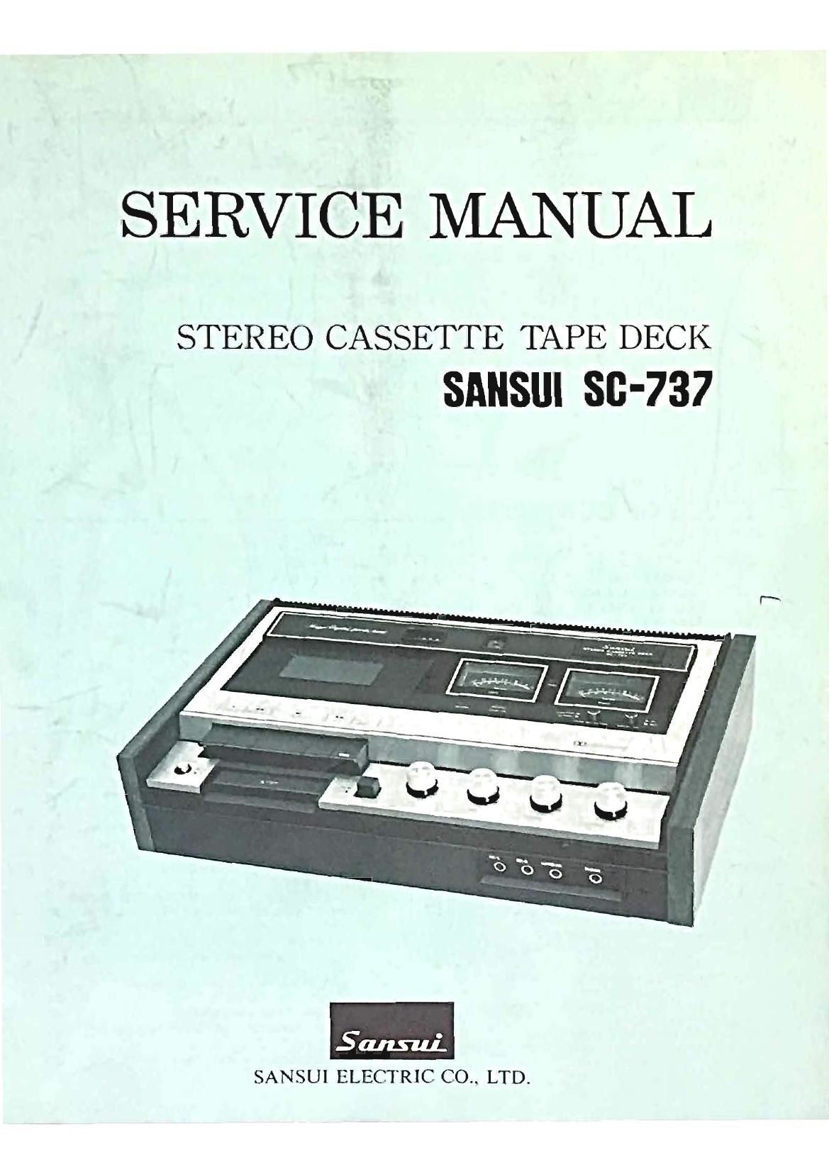
Sansui SC 737 Service Manual

This is the 36 pages manual for Sansui SC 737 Service Manual.
Read or download the pdf for free. If you want to contribute, please mail your pdfs to info@audioservicemanuals.com.

Page: 1 / 36
left right
Sansui SC 737 Service Manual

Extracted text from Sansui SC 737 Service Manual (Ocr-read)


Page 2

This service manual is designed for service engineers to repair,
adjust, maintain and order the replacement parts of the SC-737 cor-
rectly. When ordering the parts, use the stock number and parts
name specifically referring to the Exploded Views, Parts Location and

Parts List.

For general usage and maintenance of the unit, please refer to the
Operating Instructions attached with the unit.

TABLE OF CONTENTS

Section Title Page
1. SPECIFICATIONS ........................ 2
2. BLOCK DIAGRAM AND

LEVEL DIAGRAMS .................... 3
2-1. Block Diagram ........................ 3
2-2. Level Diagrams ........................ 4

. ADJUSTMENTS .......................... 5
3-1. Head Adjustment ...................... 5
3-1-1. REC/PB Head Adjustment ........ 5
3-1-2. Erase Adjustment ................ 5
3-2. Playback Level Adjustment ............ 5
3-3. VU Meter Level Adjustment ............ 5
3-4. Recording Bias Adjustment ............ 5
3-4-1. Setting TAPE SELECTOR Switch
to NORMAL .................... 5
3-4-2. Setting TAPE SELECTOR Switch
to CHROMIUM .................. 6
3-5. REC/PB Level Adjustment ., ............ 6
3-5-1. Setting TAPE SELECTOR Switch
to NORMAL .................... 6
3-5-2. Setting TAPE SELECTOR Switch
to CHROMIUM .................. 7
3-6. Dolby Circuit Adjustment .............. 7
3-7. Bias MPX Filter Adjustment ........... 7
38. Pinch-roller PreSSure Adjustment ........ 7
3-9. Torque Adjustment .................... 7
. TROUBLESHOOTING CHART ............ 8
4-1. TROUBLESHOOTING ON THE
ELECTRICAL SECTION .................. 8
4-1-1. Troubleshooting on Power
Supply Section .................. 8
4-1-2. Troubleshooting on Recording
System ........................ 8, 9
4-1-3. Playback System Troubles ...... 9. 10
4-1-4. Troubles in Both Recording/

Playback Mode .................. 10

5.

Section Title Page
4-1-5 Auto Shut-off Circuit Troubles . . . .10
4-1-6. Dolby Circuit Troubles .......... 10

4-2. TROUBLESHOOTING ON THE
MECHANICAL SECTION .............. 11
4-2-1. FAST FORWARD Inoperative ...... 11
4-2-2. REWIND lnopcrativu ............ 11
4-2-3. PAUSE inoperative ............. 11
4-2-4. Incorrect Tape Speed ............ 11
4-2-5. Excessive Wow and Flutter ........ 11
4-2-6 Incorrect Brake .................. 11
4-2-7. No Tape Movement .............. 11
PARTS LOCATIONS AND PARTS LISTS. .12
5-1. G-1159 Level Control Circuit Board ...... 12
5-2. 0-1127 REC/PB Amplifier
Circuit Board ...................... 13,14
5-3. 0-1167 Dolby Circuit Board ........ 15. 16
5-4. G-I166 Auto Shut-off Circuit Board ...... 16
5-5. 0-1168 Power Supply Circuit Board ...... 16
5-6. G-l160 Switch Circuit Board ............ 16
5-7. G-llBO CdS Circuit Board .............. 16
5-8. G-1185 Fuse Circuit Board .............. 16
5-9. Other Parts ............................ 17

. DISASSEMBLY WITH EXPLODED VIEWS.

PART LOCATIONS AND PARTS LISTS ..17
6-1. Disassembly of the Cabinet ........ 17, 18
6-2. Disassembly of the Electrical Section 19, 20
6-3. Disassembly of the Mechanism

(Top View) ........................ 21, 22

6-4. Disassembly of the Mechanism
(Bottom View) .................... 23, 24
7. SCHEMATIC DIAGRAM .................. 25
8. REPLACEMENT 0F MAIN PARTS ........ 26
9. PACKING LIST .......................... 26
10. ACCESSORY PARTS LIST ................ 26

Page 8

3-5-2. Setting TAPE SELECTOR switch to

CHROMIUM

1) Perform steps 1) through 3) of 3-51

2) Push on the PAUSE button and set the unit in the
record mode using the Chromium test tape (50-
FCR).

3) Perform steps 5), 6) and 7) of 3-5-1.

4) If the indication of output level on each channel is
under 56mV,turn VROS for L-ch and VR06 for R-ch
on 0-1127 counterclockwise or if it is over 56mV,
turn them clockwise from conductor side so that the
output level 56mV may be exactly obtained.

Repeat the above step 3) a few times until the
indication on VTVM will be exactly 56mV.

3-6. Dolby Circuit Adjustment
(See Fig. 3-4)

1) Set the MIC/LINE LEVEL volume to maximum and
DOLBY switch to OUT.

2) Turn VRO1 clockwise (viewed from the bottom side)
and VROZ counterclockwise (viewed from the bottom
side.)

3) ConnectaVTVM between the terminal01 and ground
for L-ch, and terminal 04 and ground for R-ch on
F-1167.

4) Supply the 5kHz signal from an audio signal genera-
tor to the LINE iNPUT terminals (L, R-ch).

5) Push on the PAUSE button and set the unit in the
record mode.

6) Adjust the output level volume of the audio signal
generator for obtaining 17.5mV on the VTVM.

7) Ground TP01 and TP02 and set the DOLBY switch to
lN.

8) Adjust VR03 for L-ch, and VR04 for R-ch on F-1167
until the VTVM reads 55.3mV (+10dB) higher posi-
tion from 17.5mV.

9) Disconnect TP01 and TP02 from ground.

10) Adjust VRO1 for L-ch,and VR02 tor R-ch on F-1167
until the VTVM reads 40.9mV (-2dB) lower posi-
tion from 55.3mV.

11) Ground TP01 and TP02 again.

Make sure that the VTVM connected between the
terminal 01 and ground for L-ch, and the 04 and
ground for R-ch reads 55.3mV (+2dB) higher posi-

tion.
Fig.3-4
u .
/ "=01 93,02 c. 1167A
ti
fl @ @.
° vnoa VR01 vaoz mm 0

3-7. Bias MPX Filter Adjustment
(See Fig. 3-3)

*When replacing the REC/PB amp circuit board (0-1127),

adjust the,Bias MPX Filter.

1) Set the OUTPUT LEVEL and MIC/LINE LEVEL volumes
to maximum.

2) Connect a VTVM to the LINE OUTPUT terminals
(L, R-ch).

3) Supply the 19kHz, 10mV signal from an audio signal
generator to the LINE INPUT terminals (L, R-ch).

4) Push on the PAUSE button and set the unit in the
record mode.

5) Adjust L03 for L-ch and L04 for R-ch on (3-1127 for
obtaining the minimum reading on VTVM.

3-8. Pinch-roller Pressure Adjustment

(See Fig. 3-5)

*After pushing on the PLAY button with or with0ut

cassette tape, perform the following procedures (pow-
er switch ON).

1) Hook the spring scale at point ® of the roller arm as
shown in Fig. 3-5.

2) Pull the spring scale eventually to the arrow direc-
tion until the pinch-roller stops running.

3) Slide the spring retainer (Part name, Hook, pinch-
roller spring) by loosing the screw so that the scale
indicates 330:- 30g.

4) Screw it up, then confirm that no considerable varia-
tion of the pressure indication on the scale is in-
cluded in PLAYBACK and STOP process.

capstan shaft

Fig. 3-5

3-9. Torque Adjustment

*No any torque adjustments are necessary.
Each torque is fixed as follows:

Take-up torque (PLAYBACK) ...... more than SBg-cm
Take-up torque (FAST FORWARD) ...... 60~110g-cm
Take-up torque (REWIND) ............ 60~110g-cm

Page 11

4 CHANNEL SHRED

Symptom ChecK Point

*from page 9
3) Output 560mV absent at LINE OUT

3-2. Output 275mV absent at HEADPHONE Jack

3-3. No indication on VU meter

4-1-4. Troubles in Both Recording/Playback Mode

4-1. Less high-frequency signals

4-2. Distorted or weak sound

69

70.

4-3. Excessive noise

4-1-5. Auto Shut-off Circuit Troubles
5-1. Auto Shut-off Circuit inoperative

4-1-6. Dolby Circuit Troubles

-66.
-67.

Cause & What to Do

Imperfect contact of S1-k (51-0 on 6-1127
Defective OUTPUT LEVEL volume VR6023
(VR602b)

Defective TR01, TRO3 (TR02, TRO4) on
0-1167

See 2-2 in Troubleshooting on Recmding
System

See 2-3 in Troubleshooting on Recording
System

. Dirty head

. Worn-Out head

. Loose head position

. Loose adjustment of head

. Loose adjustment of equalizer Amp.

. Defective pressure pad of cassette tape
. Defective Cassette tape

. Over input level

. Dirty head

. Loose adjustment of Head

. Improper setting of Tape Selector switch

(NORMAL or CHROMIUM) in recording

A Defective capacitor in amplifier

. Excessive tape hiss

. Defective transistor on amp. section

. Defective capacitor (resistor) or imperfect

contact.of volume control

. Due to external noise
. Magnetized head

. Defective CdS lamp MKY-SH on 6-1180
. Defective TR02, TR03, TR04 on 6-1166

Defective relay, RLOl on 6-1166

. Defective plunger solenoid P5701 on

(3-1166

. Defective DOZ, 004, D05 on 6-1166
. Defective C02, C04

As one Dolby circuit is actuated in both Recording and Playback mode by switching, the same type of trouble
may occur in both modes. In case Recording and Playback are normal, but Dolby circuit does not function, it

means that TROI, TR03 (TR02, TRO4), S1-K (S1-l), 53-3 (SS-b) are normal.

94.

6-1. Dolby circuit inoperative
(S/N ratio not improved)

6~2. Incorrect frequency response
(Excessive or less high-frequency signals)

-96.

-97.

Defective TROS, TR07 (TRO6, TR08) on
5-1167

. Defective FETO1 (FETOZ) on 6-1167

Defective or loose adjustment of VR01
(VR02) and VR03 (VR04) on~ 0-1167

Defective D01 (002), DOS, DOS (DO4, D06),
D07 (D08) on 6-1167

. Defective TRO9 (TR10) on 6-1167

IO

Page 36

SANSUI ELECTRIC CO., LTD:

14-], lemme. lzumi, Suginamlku. Tokyo 168. Japan.
TELEPHONE: (03) 3234111 / TELEX: 232-2076

SMOlO Printed In Japan (34040M)