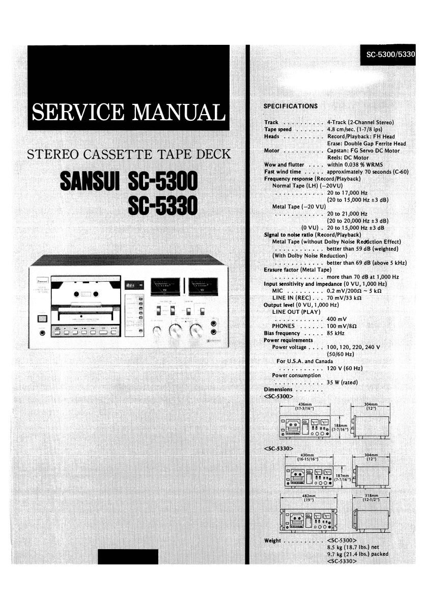
Sansui SC 5300 Service Manual

This is the 12 pages manual for Sansui SC 5300 Service Manual.
Read or download the pdf for free. If you want to contribute, please mail your pdfs to info@audioservicemanuals.com.

Page: 1 / 12
left right
Sansui SC 5300 Service Manual

Extracted text from Sansui SC 5300 Service Manual (Ocr-read)


Page 2

805300/5330

1. BLOCK DIAGRAM

6 Recording Operation (L-CH)


Dc FLAT AMP
Ec vae \\ um LEVEL
ch --£>DC+ 7- e w, agent RELAY Rm
w 31- pm , w , sax 3 mg
T o
/ weep 0 t 5
R521? REC P5 / / _° PM 1 m HEADPHONE AMP
REC DC 1 _opc+
1 PHONES
we 5, RELM fl 0W
.m . t r
Pa t DRlVE / 42 Fl]
we LEVEL Eéfiflgfic v
t METER AMP
i W FOR PB Ea t To VRos W METER
LINE LEVEL 1 553%,»?
LINE t
leuY View My EO SELECT
than V i COMPARATOR PEAK lNDICATOR
NORM o t a LED DPlVER u
"T \- - "A ll
l
t . DEFEAT v
i l5¢oz D
t o 1 n
LFos 0N HM
,__t, Icot k 4 s, ,, _ 7
EtEcwomc SWlTCN
woc- , row we MUTE
ELEcmowc
swrrcN .L Q\_Ooct
NErAt Eon BlAS 5.
"EC W MAGNET COUNTER r 06*
Norm
BIAS sEtEcT gwymt
ERAS: HEAD CAPSTAN G); tchc CONTROL
MOTOR
REEL FUNCTION
Moroa ® swurcn
ILME first) PLAV REC
PLUNGER PLuNGEn PLUNGER W

2. OPERATION

2.1_ Operation of E|ectric Circuits (Refer to b|ock is not appeared for approximately 0.5 second in order to protect

. . . the tape and the sets mechanisms. Terminals other than those
tic dla ram.
diagram and SChema g ) just stated start operating immediately For example, if the

1- Functions and Operations of CMOS LSI Employed in PAUSE mode is released either in the REC PAUSE mode or
Logic Control Circuit PLAY PAUSE mode, each output changes over immediately
In these models, Full Logic Feather Touch Control is realized by when the PAUSE button is depressed, The stop duration of
using a logic control circuit whose main components are OM05 LSl operations is determined by the C and R connected to the OSC
(Model TC9121P) and plunger solenoids. terminal,
The function and operation of the TC-91 2] P are as follows: 0 When power is switched on, the mode is shifted to STOP auto-
0 Regarding the respective modes, operation is actuated when the maticallyt
LSI input is dropped instantaneously to the L4evel. The opera- I Automatic recording and automatic playback based on the use
tion is sustained until the set is changed over to next mode. Of a timer are pUSSiblc-
I A circuit preventing troubles caused by multiple-pushing of 0 Owing to the large current capacity of LSI, the control of the
input keys is provided in the LSl. (Refer to Table Fig. 2-2.) motor and plunger is easier. The LEDs indicating the respective
0 Although the mode of PLAY, REC, REW, F.F. and MUT output modes can be lighted up directly.
terminals of LSI whether H or L can be changed directly, output
Fig. 2-1 Fig. 2-2 Fig. 2-3
Top View & pin function of IC TC-9121P Mode produced by multiple-pushing of keys Mode of each output terminal for each key input
(The "0 mark indicates the H-level output.)
Mn t U 211 tat «.ytm. om, h, um mu m. W m w nus:
NEW 2 23 PE END STOP FEW, FF PLAY. REC, PAUSE STOP M 0;th m STD? FF REV PLV PLA' svol PLAY :Efic
FF 2 22 on
PLAY 4 Keylneui ZlOVREW FF NEW, PLAY STOP 15 OVPLAV O C
an s 20 mm REw. PAUSE FF is CHIC C Q
570 5 fiiwat 9 OPVSE REW Er. PLAY sroc iT U-STOP Q C O O O O O
PAUSE 7 13 errr/niw REC. PAUSE NEW in (HF/new O O
AVPEW 8 l7 OVSTOP
WW 9 Norm my PAUSE my PAUSE l9 OEPAUSE o O O
x to ifiilitli ts pew REC Pm REC 20 0-wr 0 o t; O
r u "me 14 INN muse must 2] ome O
1 2 3 °5c my t. nus: REC PAUSE 22 on 0
Example: u, the F.F. Key and REW Key are depressed together, 23 mean 0 O O O O O O O

the output mode will mute to STOP". oh the pthet
map when thz REC and rLAv keys ate depressed to»
gethet, the oulpul mode becomes REC".

Note The output or O-FF/REW has the tuhciion pr aEcelerzling the
motor speed in F.F. and REW npetatian. and Al the same
time, of ptmtttittg tho PtAv indicator LEDfrom liming up.