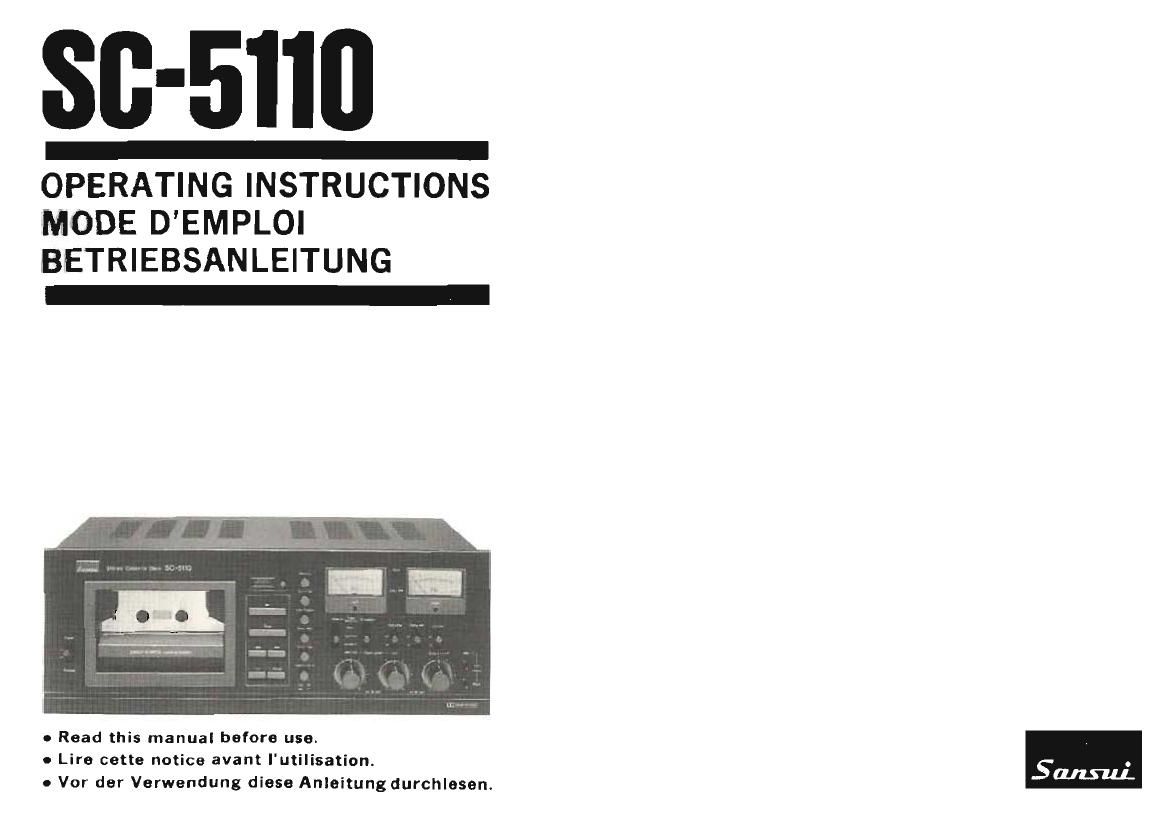
Sansui SC 5110 Owners Manual

This is the 50 pages manual for Sansui SC 5110 Owners Manual.
Read or download the pdf for free. If you want to contribute, please mail your pdfs to info@audioservicemanuals.com.

Page: 1 / 50
left right
Sansui SC 5110 Owners Manual

Extracted text from Sansui SC 5110 Owners Manual (Ocr-read)


Page 1

80-5110

OPERATING INSTRUCTIONS
MODE DEMPLOI
BETRIEBSANLEITUNG

o Read this manual before use.
0 Lire cette notice avant I'utilisation.
o Vor der Verwendung diese Anleitungdurchlesen.

Page 2

For the United Kingdom only

Important

The wires in this mains lead are coloured in accord-
ance with the following code:

Blue: Neutral

Brown: Live
If the colours of the wires in the mains lead of this
equipment should not correspond to the coloured
markings identifying the terminals in your plug, pro-
ceed as follows:

The wire which is coloured blue must be connected
to the terminal which is marked with the letter N'
or coloured black.

The wire which is coloured brown must be connected
to the terminal which is marked with the letter 'L' or
coloured red.

Ensure that your equipment is connected correctly.
If you are in any doubt, consult a qualified electrician.

For equipment purchased outside the U.K. with a
"EUROPEAN" two-pin mains plug, the plug should
be removed and connections made in accordance with
the above instructions. Ensure also that the equipment
is properly adjusted to 240 volts operation. if you are
in any doubt, consult a qualified electrician, or our
Service Agent in the U_K.

We are grateful for your choice of the Sansui SC-51iO stereo cassette
tape deck,
Before you begin to operate it, may we suggest that you read this
booklet of operating instructions once carefully? You will then be able
to connect and operate it correctly, and enjoy its superb performance
for years.

Table of contents

Precautions ................................. 4
Features ................................... 6
Connection ................................. 10
Panel information ............................. 14
Operation .................................. 26
Some useful hints ............................. 40
Specifications ................................ 44
Conditions mistaken fO' breakdowns .................. 46

WARNIN6175 :"-;.-'<'11 lire or Shock hazard,

do not it: ; appliance to rain or

moisture.

. The Model No and Serial No. of your unit are shown on its back

paneL
0 Do not lose the Warranty Card that carries your units Model No.
and Serial No.

Page 18

18

TAPE SELECTOR position
Position TAPE SELECTOR
TAPE SELECTOR Position

" . MODE r REC PLAY
MANIERE ENR REPRO

' \ \ BTRIEBSART AUFNAHME WIEDERGABE

»TAPE . 7 . a

BANDE _ TAPE SELECTOR BIAS, EOUALIZER EOUALIZER

l TON BAND x
LSUFER COLOR

AGFA

SUPER FERRO
DYNAMIC
r Lt»)
BASF 7 7 7
LH SUPER
LFL
FUJI FILM
FX-i
l U l
MAXELL
LD~XL 1
L W i nornn lLHI normal (LH)
SCOTCH MASTER I. .
LOWNOIhL
SONY '
HF
D
TDK l' _
E.)
1H
COLUMBIA 7 i "
[XQ
AGFA LSTEREO CHROM
BASF ISCH .
MAXELL UD»XL U 7 4
SONY CH high (CIOg) high (001)
TDK NEW )A
FUJI FILM FX-n
SCOTCH MASTER I] l 7
AGFA (VAR/AT
BASF FCR
SCOTCH MASTER [I] Fe-Cr Fe-Cr
EONY ' DIJAD
COLUMBIA DX5 i,
TDK l AD 7
BASF l L"H norma, tLrl) high (CrOz)

EAXELC i uni _ A

Ti

13 MIC/DIN INPUT LEVEL Controls and Marker

These controls adjust the input signal level from the MIC jacks and the
REC/PLAY (DlN) socket. When making a monophonic recording with
just one microphone plugged into the MIC-LEFT (MONO) jack, the
signal from the microphone will be recorded with equal strength on the
two channels if both the RIGHT and LEFT controls are in the same
position. By increasing one or the other level control,the sound image
may be moved. The back control is for the right channel, the front for
the left channel. The Marker is very convenient for remembering a
particular control setting.

14 BIAS Switch

15 EOUALIZER Switch

The two TAPE SELECTOR switches should be switched over to the
correct position, depending on the type of tape used. Set the BIAS _
switch prior to recording and the EOUALIZER switch prior to re-
cording or playback. Select the position of the TAPE SELECTOR
switches as shown in the chart.

16 LINE INPUT LEVEL Controls and Marker

These controls adjust the s};': the LINE IN (REC) terminals.
The back control is (or the ' "it and the front control is for
the left channel. The Marker ' very convenient for remembering a
particular control setting or ".r marking TBdB the proper place to set

these controls for receiving l3 _ _.-, CV broadcasts.