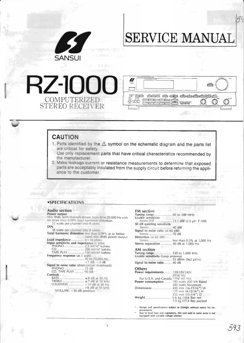
Sansui RZ 1000 REC Service Manual

This is the 18 pages manual for Sansui RZ 1000 REC Service Manual.
Read or download the pdf for free. If you want to contribute, please mail your pdfs to info@audioservicemanuals.com.

Page: 1 / 18
left right
Sansui RZ 1000 REC Service Manual

Extracted text from Sansui RZ 1000 REC Service Manual (Ocr-read)


Page 2

RZ-1000

4. ADJUSTMENT

4-1. Bias Adjustment of Power Amp. (See Parts Laocation F6007 on page a and mom on page 7)

Note: 1, Master Volume...
2. Room Temperature. ..
3 For this adwstment, run the unit i'or more than 5
minutes after the power is switched ON,
4.Betore turning ON power switch, set kVRi on
F6007 to center position.

. ........ Minimum

. 18°C~ 28°C (65°F~83°F)

SUBJECT |

STEP MEASURE OUTPUT ADJUST ADJUST FOR i REMARKS
1. l Bias Current Ad). LVCH Between Foint® & Point® kVRl, LVCH DC 8.5~9,3mV Tltls bias value is convened
< Between emitters of power (F6007) i from current value to voltage
transistor thlZ & kQIZ), by ohms law.
F76001>, DC Volt Meter
2. Bias Current Adj. RVCH l Between Pointé & Point® kVR], R-CH l DC 8.5~9,5m\/
< Between emitters of power (F-6007)
transistor WOW 3. in3l,
F-GOOi >, DC Voii Meter 1
4-2. FM Adj-USUHEHI (See Parts Location F-6001 on page 7)
STEREO so Fig, 44
our
D MMV
'_° FM 556 ANUTENNA umr oisr METER
°._o 33 m i5kHz [PF
00! DE 00' ANY OUT ..
3 m we. .t ii. ouro__,t_
AUDIO osc
VTVM
7
--O
1) FM IF & Reference Frequency Adjustment
Note: 1. SELECTOR . ... FM
2 . FM MUTINC/MODE. ,. OFF/MONO
FEED SIGNAL i
STEP SUBlECT - - n ' *fi MEASURE OUTPUT ADJUST ADJUST FOR REMARKS
FROM TO
1 Reference V0 Input i l Between Pomtt: tTCi lOBJVtHz: iOOHz
Frequency Adj, Tune to 98MHz) (Pin i of Front-end, (F6001)
room a Ground)
l Freq. counter 7 7 I
Z. Discriminator 1 98MHZ ANT lnnut ANT l Between Point 5 Kt dTi DC 0\t30mV 'Repeat procedures
Cnii adj. 63dBt i59 8dBi, . Terminal Priiintigi @6001) as stated in subject
. kHZ (100% MUDJ. 3009 Buoss de7, F-EOU.) l & 2
. H1 556 DC Volt Meter
.7, . . _ . 7 . i
2 Same as above Same as l REC OUT L or RVCH, 0T2 :viin. THD
, abme Dist Meter & Scope *F»600i)

oTechnical Hint for FM Adjustment

There are two kind in indication of FM 556 output attenuator.
I. Attenuator with marking of 759 open .............. open indication

type.

2. Attenuator with marking oi 75!) load or close .....

I The following table shows relations among FM SC attenuator indi-
cation (dB), available power ratio (dBt) and antenna terminal vol-
tage [d B/uV) in each iriutcat on type,

or close indication type

cation t) De

........ load

. FM 56 Available l Antenna

FM 56 output level in this PM Atliustment are described as open indie Attenuator Power Terminal

indication Ratio Voltage

To feed FM Signal, a dummy antenna cirCUit as Fig 3-1 must be con» . . t 0 dB -0 8 dBf -6 dB/uV
nected between FM so output and ANT terminal iaoom oi the unit. 996" '"dcamn We 7i dti _ .7 auger so (ta/ti,

Load or close 0 dB 5.2 dBf 0 dB/ttV

indication type 60 dB 65.2 dBl 60 dB/itv

Dummy antenna