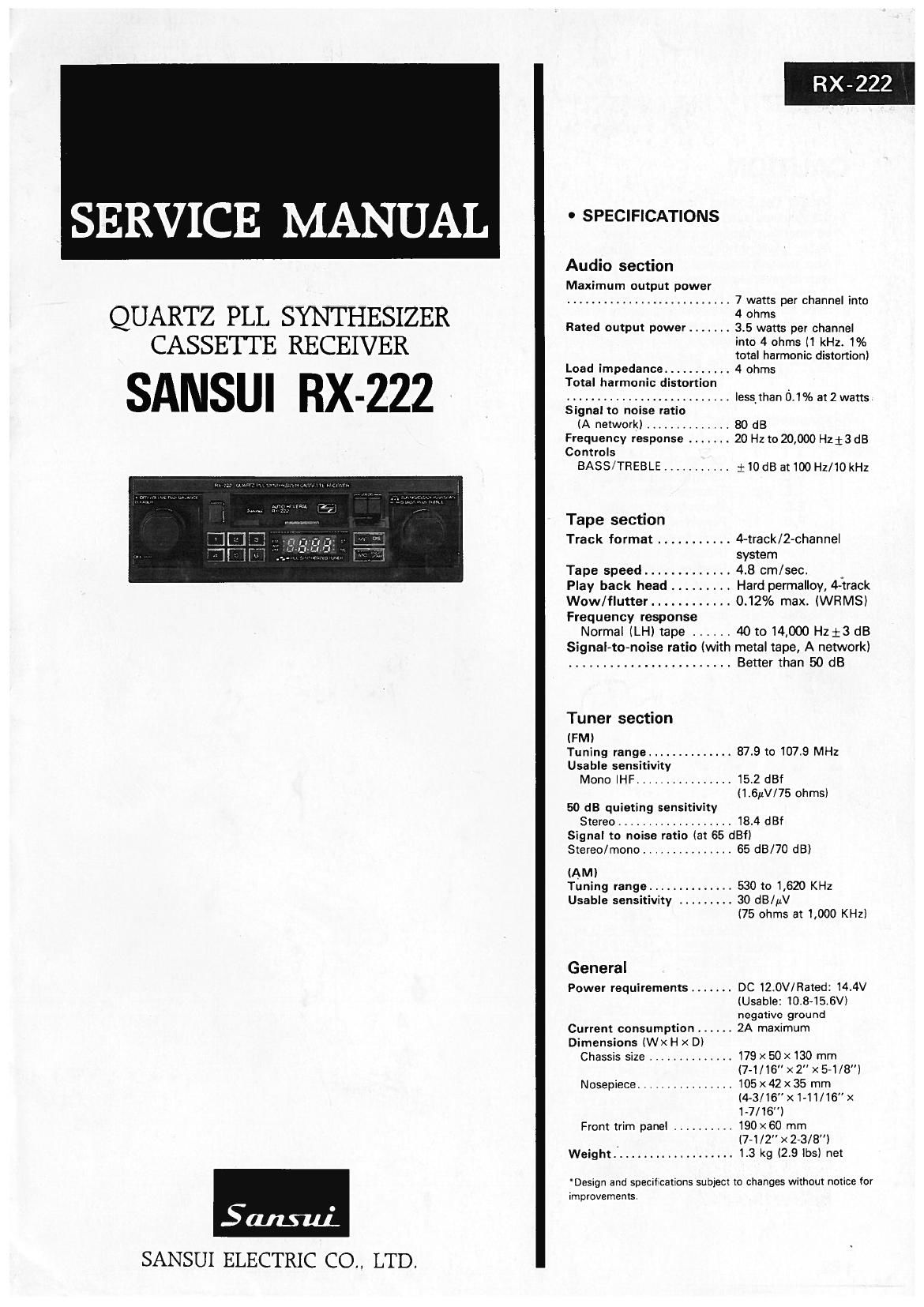
Sansui RX 222 Service Manual

This is the 26 pages manual for Sansui RX 222 Service Manual.
Read or download the pdf for free. If you want to contribute, please mail your pdfs to info@audioservicemanuals.com.

Page: 1 / 26
left right
Sansui RX 222 Service Manual

Extracted text from Sansui RX 222 Service Manual (Ocr-read)


Page 1

RX-222

SERVICE MANUAL . SPECIFICATIONS

Audio section

Maximum output power
........................... 7 watts per channel into

QUARTZ PLL SYNTHESIZER 4 ohms

Rated output power ....... 3.5 watts per channel

CASSETTE RECEIVER into 4 ohms (1 kHz. 1%

total harmonic distortion)

Load impedance ........... 4 ohms
Total harmonic distortion
_ ........................... less than 0.1% at 2 watts
Signal to noise ratio
(A network) .............. 80 dB
Frequency response ....... 20 Hz to 20,000 H213 dB
Controls
BASS/TREBLE ........... $10 dB at100 Hz/1O kHz

Tape section

Track format ........... 4-track/2-channel
system

Tape speed ............. 4.8 cm/sec.
Play back head ......... Hard permalloy, 4-track
Wow/flutter ............ 0.12% max. (WRMS)
Frequency response

Normal (LH) tape ...... 40 to 14,000 Hzi3 dB
Signal-to-noise ratio (with metal tape, A network)
........................ Better than 50 dB

Tuner section

(FM)
Tuning range .............. 87.9 to 107.9 MHz
Usable sensitivity

Mono IHF ................ 15.2 dBf

(1.6uV/75 ohms)
50 dB quieting sensitivity

Stereo ................... 18.4 dBf
Signal to noise ratio (at 65 dBf)
Stereo/mono ............... 65 dB/7O dB)
(AM)
Tuning range .............. 530 to 1,620 KHz
Usable sensitivity ......... 30 dB/pV

(75 ohms at 1,000 KHz)

General
Power requirements ....... DC 12.0V/Rated: 14.4V
(Usable: 10.8-15.6V)
negative ground
Current consumption ...... 2A maximum
Dimensions (Wx H x D)
Chassis size .............. 179 x 50 x 130 mm
(7-1/16" x2" x5-1/8")
Nosepiece ................ 105 x 42 x 35 mm
(4-3/16" x1-11/16" x
1-7/16)
Front trim panel .......... 190 x60 mm
_ (7-1/2 x2-3/8)
Weight .................... 1.3 kg (2.9 lbs) net

Design and specifications subject to changes without notice for
improvements.

Samui.

SANSUI ELECTRIC CO., LTD.

Page 2

CAUTION

1. Do Not Use Endless Tapes
If an endless tape is used with this unit, the tape will not
be wound up properly inside the cassette shell and, as a
result, it will not be possible to use it again.
Also, this unit cannot eject a tape which has been inserted
with its reverse side facing up.
(At this case, refer to How to hook out the endless tapes.)
2. Since some capacitors and resistors are omitted from parts
lists in this service manual, refer to the Common Parts List
for capacitors 8 resistors, which was issued on June 1987.

3. Abbreviations in this service manual are as follows.

e Abbreviations List

R. Carbon Resistor
C.C. . Ceramic Capacitor
T.C. : Trimmer Capacitor
E.C. : Electrolytic Capacitor
P.C. : Polystyrene Capacitor
V.R. : Variable Resistor
(Rotary Volume)
R.V. : Resistor Variable
(Semi-Fixed Resistor)
SW. : Switch
JW. : Jumper Wire

Page 21

RX-222

EXPLANATION OF INPUT AND OUTPUT TERMINALS

E01 to E02 These threelstate outputs are used (via active filters) to supply analog voltage; toi the tuner varicap tor
controiling the local oscilators.
CE This-input is used to designate the stand-by mode to the chip. It is low to designate the stand-by mode.
(display: off, PLL: disable)
PSC This output is used to control the division ratio of the FM two-modulus prescaler (pP8553AC).
X1, X2 These inputs are for connection to a 4.5MHz crystal.
SD This input is used to control the automatic station searching operation. It is high to indicate the presence
of a station.
MUTE This output line is high to mute the radio in the case of station change, band change, and so on.
D1 to D5 These outputs are used as digit drives for the display. (Active high)
VDD This is a 4.5 to 5.5 volt supply for the chip.
a to 9 These outputs are used as segment drivers for .the display. They are also used as vertical drive for the
control key and mode switch matrix. (Active high)
K0 to K3 These inputs are from seven by four matrix. Various functions are entered through the matrix.
See Fig. 2 for the matrix assignments.
FM This is the FM band local oscilator input. The frequency is divided by 16/17 using a two-modulus
prescaler (,uP8553AC).
GND System ground.
AM This is the AM band local oscilator input.

20

Page 26

10. PACKING LIST

RX-222

NO. STOCK NO. DESCRIPTION" "0771 No. STOCK No.1 .. DESCRIPTION ¥ QTY
1 TA000160 TRIM. PLATE 1 10 TA000169 6P CONNECTOR ASS'Y 1
2 TA000161 COVER. FIXTURE 2 11 TA000169 4P CONNECTOR ASS'Y 1
3 TA000162 KNOB. ROTARY (F) 2 12 TA000169 ACCESSORY ASSY 1
4 TA000163 KNOB. ROTARY (R) 2 12-1 TA000169 BOLT, HEX M5><12¥ 1
5 TAOOO164 BRACKET. MOUNTING 1 12-2 TA000169 WASHER, PLAIN 4
6 TA000165 PAD. SNOW 2 12-3 TA000169 NUT HEX 3/8 4
7 TA000166 BOX. GIFT 1 12-4 TA000169 NUT HEX M5 2
8 TAooo167 MANUAL INSTRUCTION 1 12-5 TA000169 WASHER TOOTHED 2
9 TA000168 POLY. BAG (SET) 1


\ "
"/
N

{2

if PAQKIflfi L SI

o STOCK No DESCRIPTION dTY
I srTseozaAn TRIM. PLATE I
2 snoaossoo COVER.FIXTURE 2
3 97T|30|7l0 KNOB . ROTARY(F) 2
4 91TI3033I0 KNOB.ROTARY(R) 2
5 97124014 so BRACKETMOU I
s 97T49ossoo PAD.SNOW 2
7 97T50083A0 BOX.G|FT I
a 971 950 44 A o {NAQ-Péfimm I
9 97T4eozvo PWT) 1
IO 97TOB O4|00 6F CONNECTORAfitl _
II 97Teaoasoo "com I
12 - AcczssoRY Ass'Y

I2-I 97T3l003l0 BOLT. HEX N5xI I

I2-2 571 3 I004 Io WAWJLAIN 4

I2-3 91T3I002Io NUT HEX ya 4

I2-4 739I5000H NuT HEX N5 2

[2-5 74022050I I WASHER mama: 2

l3 97T4906200 PAD SHAFT 2

25