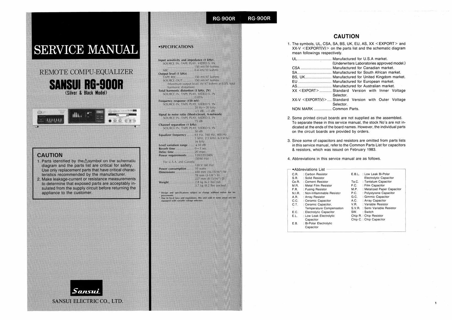
Sansui RG 900R Service Manual

This is the 20 pages manual for Sansui RG 900R Service Manual.
Read or download the pdf for free. If you want to contribute, please mail your pdfs to info@audioservicemanuals.com.

Page: 1 / 20
left right
Sansui RG 900R Service Manual

Extracted text from Sansui RG 900R Service Manual (Ocr-read)


Page 1

RG-SOOR

' -Abbreviations List

CAUTION

. The symbols, UL, CSA, SA, BS, UK, EU, AS, XX and

XX-V on the parts list and the schematic diagram
mean followings respectively.

UL ............................... Manufactured for U.S.A market.
(Underwriters Laboratories approved model.)

CSA .. Manufactured for Canadian market.

SA ..... Manufactured for South African market.
BS, UK. . Manufactured for United Kingdom market.
EU ....... . Manufactured for European market.

AS ......................
XX < EXPORT> ..

. Manufactured for Australian market.

.Standard Version with Inner Voltage

Selector.

XX-V ....Standard Version with Outer Voltage
Selector.

NON MARK ................ Common Parts.

. Some printed circuit boards are not supplied as the assembled.

To separate these in this service manual, the stock Nos are not in«
dicated at the ends of the board names. However, the individual parts
on the circuit boards are provided by orders.

. Since some of capacitors and resistors are omitted from parts lists

in this service manual, refer to the Common Parts List for capacitors
& resistors, which was issued on February 1983.

. Abbreviations in this service manual are as follows.

C.R. : Carbon Resistor E.B.L. : Low Leak Bi»Polar

SR. : Solid Resistor Electrolytic Capacitor

Ce.R. : Cement Resistor Tac. : Tantalum Capacitor

MR. : Metal Film Resistor P.C. : Film Capacitor

F.R. : Fusing Resistor MP. : Metalized Paper Capacitor

N.l.R. : Non-inflammable Resistor P.C. : Polystyrene Capacitor

AR. : Array Resistor G.C. : Gimmic Capacitor

C.C. : Ceramic Capacitor A.C. : Array Capacitor

C.T. : Ceramic Capacitor, V.R, : Variable Resistor

' Temperature Compensation S.V.R. : Semi Variable Resistor

EC. : Electrolytic Capacitor SW. : Switch

E.L. : Low Leak Electrolytic Chip R. : Chip Resistor
Capacitor Chip C. : Chip Capacitor

E.B. : Bi-Polar Electrolytic
Capacitor

Page 2

1. BLOCK DIAGRAM

RG-900R

(luv u)

IdBVIG'DiI
HOOSSH
sseIaiiM

iauoauoo aiomag

Ira

'lE/IET DIW

iaAb

dmv 3m

9
NI 030M

C

.LI'IO
030M


NI (7|ng

IOO

NI 5 030M

030M
9?)
C0)

NI saunas

I
v

030M
ozsa

H?
m
. i s
13
to ~ g
- M s 535:; 2
i... H 20.
as n m "In
to -
5w 5; ? a
ago «0 s 63H: L
gml S Ki 9
fl : N r-iii 'I M
9m .1 5 I 3&5 l ISOHI % V E
4:" I p 33 l «mom I; E
i o i}; < I -* n
a i; o m l IIKHI ;
x i I 3 I: N
" ° I: a I n :u 9
.,. = N .. (SEL5) a n I N : 2.5KHz
... . 3 I on m A a .p H
H'7_7 0|
0 m ._ 5 (DATA) 2 6.3KH1 9
I: . 7-... u' l' x _,
amgn " 5° 4 KH u__ E
ago- - (UP) 3.3 IG 1 .. 0,
:90? ~ 3.
2:0 _m (DATA s.
:v A <0uwN> n 69 >
H 04
(Guzm) 21
_ _: <
a .m. 33
a a a :e .L-."
0 r 1:0 I-i
)> 5 mm o
5 1 m
3 E s-®-o s
11. ,
g 8
g
- 2 so 35
g :0) g_ 3? __g
m a: a _. 3%
3 In < r2
\fio A g No:
ram 0 ~ N5
ac;> P 2
8 E 2
> g : l-F-l
.2, p m I~_
E E V 7 I?) :-
h z < 8
:n E N
V _
IL
23
a a 3 ; 5'2 e S:
a a a 3 ;I2 3 s
~ ~ N ya a _
at 04 N u N is N 8 a A ' Z _
_ a .9 a: .. a. u ; g 4 m 5
.1 n m gI _ :1
WE EM». 5i 1 I \rr/i g o 7..
o
c. s a 3 6 X a a
- ~ ~- g _
2 a S
u) 5 .3 N
9. 5»? _ m
DUDDU a G :
DDUDDDDDU 3 3
,,
DUUDUUUD .-
DDDU .. D . .< s; g
c
DDDUUD m o g > :5 203:, c
arm 2 <5 % o x 3% 098 8 5;
Q g U 0:, ° 11; m
2 _] o m 0 3 o
2 2:! c n c c
o m m a a
i- n r
m m

z I> Jkl
ml

i

RG-900R

2. DESCRIPTION OF GRAPHIC

1. Pin Arrangement
'LC7060 (Graphic Equalizer Controller IC)

K25: v

KSE
SENS]:
sw II:
ssz

42 Kl

4I K0

Evan
Elm
Em

SWBE 37 DATA
REMOTE E '3__6I CLOCK
SW4E 35 T7

Ere
Era

swsE
sws [E

4

BUZZERE LC7060 32 T
VR up IE 3| T3
VR DOWNII: 30 T2
SEL5E 29 TI

SELI E TU
SELZ EPhono
SEL3 Eco
SEL4 IE TA
T IE
TEST [E
Vss E

E To
film
26 MUTE
E] FM/AM
El SCAN
E] oscz
:23 osu

2. Description of Terminals
(1) K. to Ki and Tu to T7 Configure a key matrix.

I I I I L I
am HEHLD
Koe II - if) e M] w M5 SELI SEL5~ UP am
I T I
_ FM GEO #FJILD *
Kl (2 i6 M2 FLAT SELZ KM DOWN mm
| i i
K2~ l3 a H -l M3 MUTE-iSEL3 Iii 22"-
I I I L
_ G _ VR _
K3v- l4 eMEMO M4 /S I-SELA SCAN DOWN DIMMER
I I I I
To TI T2 T3 T4 T5 T6 T7
' x
7 :> .
I
(2)5ENS(I)

This terminaI is used for checking whether backup function is reset
or not when power is turned on, If at "H when the power is on, this
indicatesthatthe backrupfunrnion is reset, ifat L, this Indicates that
inItIaIIzation is made when power is turned on.

(3) REMOTE (I)
This terminal is used for inputting remote-control signals,

EOUALIZER

CONTROLLER IC, LC7060

(4) SW1 to SW6 (I)
Functions of these switches are listed below.
Items on each key function)

(For further detaII, see

IEW Np.I Function I L" I '
SW1 Designation of the User User
number of users memory:2 memory:5
memory units Maker I
option:3
SW2 Switching of GEO LC7520 LC7522
electronic variable I
resistor ICs LC7520 I
and LC7522.
SW3 Switching of display LC7565 LC7560
IICs LC7565 and
LC7560./ SW4 Switching of 6/8 key If SW5 is at IThe present
functions L, GEO is mode Iauto
displayed for mode or GEO
5 seconds. display mode)
I If sws is at is displayed.
I H", the I
I present mode
g is displayed. /
SW5 Switching of memory Memory disr Memory dIST
display flashing on/off play flashes. play stays on.
and memory number Memorv:5 + 3
funetion specification LC7820 is
7 i #ngi i *7 i 7 usaiblelr
SW6 Switching of display GEO controller Setting of
IC for using it as usually SPEANA dis
ISPEANA display only I Iplay when
I_ l Ipower is on

*Auto-mode: GEO is displayed when G/S key is depressed.
After 5 sec, SPEANA is displayed automatically.
GEO display mode: GEO is displayed fixedly.

(5) BUZZER (6)

This terminal is used for actuating a piezoelectric buzzer. When keys
are operated, a signal having a frequency of several-hundred hertz is
outputted from this terminal.

(6) VR UP/DOWN (6)

These terminaIs are used for outputting a signal for activating an elecr
tronic variabIe resistor.

When VR UP/DOWN keys are depressed, and "H" pulse is outputted
for 0.l sec from each port corresponding to the depressed key.

(7) SEL 1 to 5 (6)

These terminaIs are used for outputting a signal for switching functions.

SEL l to 4 .. When SEL l to SEL 4 are depressed, an "ll" pulse
Is outputted for 03 sec from each port,

SEL S ................ When SEL 5 key Is depressed, the terminal output Sig;
naI is cyclically inversed. When SELI to 4 are being
selected, the signai is at ".L

(a) FM/AM (6)
ThIs terminal Is used for switching tuner bands. When FM/AM key is
depressed, an "H puIse is outputted for 0.} sec.

(9) SCAN (6)
This terminaI is used for outputting a tuner scannIng signaI.
key is depressed, an H pulse is outputted for 0.3 sec

When SCAN

(10) MUTE, MUTE (6)

These terminals are used for outputting a mute signal. When MUTE
key is depressed, the signal is at ii.

When not depressed, the signaI is at L MTTE terminal is IogicaIIy
reverse of MUTE.