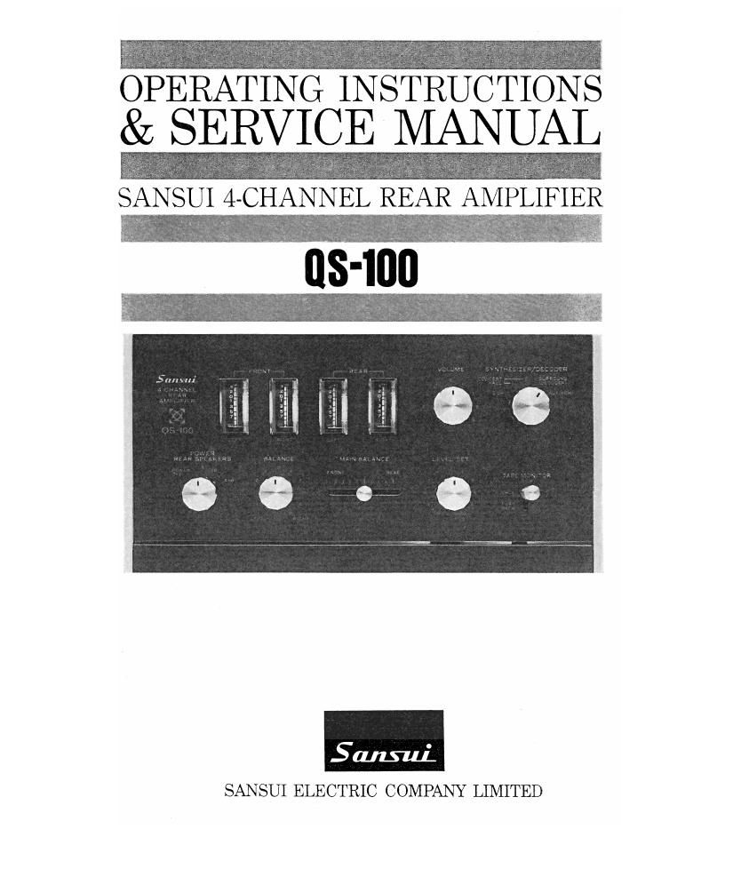
Sansui QS 100 Service Manual

This is the 22 pages manual for Sansui QS 100 Service Manual.
Read or download the pdf for free. If you want to contribute, please mail your pdfs to info@audioservicemanuals.com.

Page: 1 / 22
left right
Sansui QS 100 Service Manual

Extracted text from Sansui QS 100 Service Manual (Ocr-read)


Page 2

Congratulations on joining the thousands of proud, satisfied owners of
quality stereo components from Sansui.

The QS-lOO is a marvelous combination of Sansuis unique QS matrix
and phase modulator circuit (patents pending) that produces a multi-
dimensional sound field so enthusiastically received by many audio
experts as purely revolutionary, and a quality 50 watt power amplifier
for the rear channels. An instrument that literally heralds the new age
of 4-channel stereo sound reproduction, the QS-lOO not only converts
your present collection of 2-channel stereo records and tapes, as well as
FM multiplex stereo broadcasts, to immensely richer 4-channel stereo
sound, but, working in the capacity of a decoder, restores any 2-channel
material encoded from four channels by the Sansui 4-Channel Encoder
(recording matrix) to its original full-fledged 4-channel status.

Simply add the QS-lOO to your present 2-channel stereo along with
a second pair of speaker systems, and youll instantly have a 4-channel
stereo system that gives you far greater pleasure both in sound effect and
such technicalities as the choice of speaker positions.

Before you rush to audition how your new possession actually fills your
room with the vibrant atmosphere of live performances, may we suggest
that you read through this booklet once and acquire basic knowledge
about its operation. Then youll be better prepared to enjoy exciting
4-channel stereo at its best for years to come.

CONTENTS

SWITCHES AND CONTROLS .............................. 3, 4
CONNECTIONS ............................................ 5, 6, 7
TO ENJOY 4-CHANNEL STEREO AT ITS BEST ........ 8
ADJUSTMENTS ................................................ 9
OPERATION .................................................... 10
SIMPLE MAINTENANCE HINTS ...................... 11, 12
SCHEMTIC DIAGRAM .................................. 13, 14
TEST POINTS/ABOUT SERVICING/ACCESSORIES .. 15
ALIGNMENT .................................................. 16
SPECIFICATIONS/DISASSEMBLY PROCEDURE ........ 17

PRINTED CIRCUIT BOARDS AND PARTS LIST
............................................ 18 19, 20, 21, 22

OTHER PARTS AND THEIR POSITIONS ON CHASSIS
........................................................ 23 24

Page 21

W: Parts N0.

X: Parts Name Y: Stock N01

OTHER PARTS

W 1 X Y

R701 1 470m 1 0101474
1 R702 1 4701:) j 0101474
1 R703 1 470m 1 0101474
R704 1 470k!) 1 0101474

R705 100m 0101104

R705 100m 1 0101104

: R931 13sz 0101823
1 R932 82m :10% %w CR, 0101823
R933 1 53m 1 0101683

R934 1 68m ; 0101683

R935 1 2719 0101273

R936 1 2719 0101273

R937 1 10110 0101103

R933 101!) 0101103

R939 1210 0101123
VR501~504 250kfl(MN) x2 M0111 Enhance 1 1040130
VR505~5osT 250m1MN) x 2 Balance 1 1060050
VR509~512 25019.14) :< 4 Volume 1 1060060
VR513, 514 250mm) x 2 Rear Lem 1 1015040
WW, 9031 2501910):-: 2 13151 5131 1010710
C010 001,111 333% 1.4kV CC. 0659801

T001 1 Power Tvonsformer 1 4000980

51 <11, 1,1 Tape Monimr 5w11c11 1 1170170

$210~1>1 Y-3-6-5 Funcnon Sw'11c11 1103380
SHONE 11144 Power/RearSpeake'ESwnc'n 1101290

L001 DIN Jack 2430040
7#_"7fi"m A PU001 Voltage 5315001 Socket 2410080
, PU002 Vo11age Selector P109 2410090
; 7 r C0001 AC 001191 2450041)
1
1 1
M501 1 4300450
. , M502 Leve1 Meer 1 4300450
1 . M503 11 ' 1 4300450
M504 4300450
, , :4 F091 1 2A Power Fuse (For 100N117 0431242
1 115A Power Fuse (For 222N240V) 0431232

2-23A