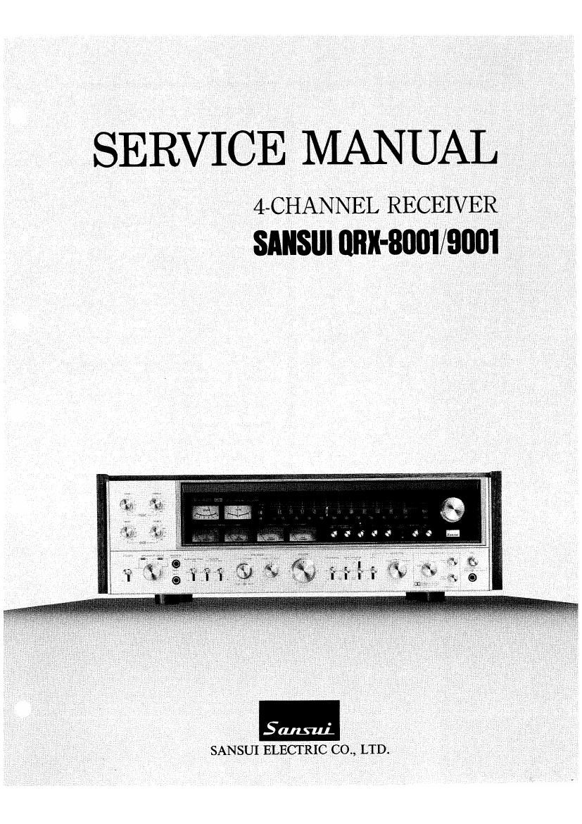
Sansui QRX 8001 9001 Service Manual

This is the 28 pages manual for Sansui QRX 8001 9001 Service Manual.
Read or download the pdf for free. If you want to contribute, please mail your pdfs to info@audioservicemanuals.com.

Page: 1 / 28
left right
Sansui QRX 8001 9001 Service Manual

Extracted text from Sansui QRX 8001 9001 Service Manual (Ocr-read)


Page 2

TABLE OF CONTENTS

Section Title Page

1. SPECIFICATIONS ......
2. BLOCK DIAGRAM
2- 1. QRX-8001
2- 2. QRX- 9001
3. OPERATION OF FM DOLBY SYSTEM
4. ADJUSTMENTS .....
4- 1 Audio Section .
4- 2 Tuner Section .. ,8.9.10.
4- 3. Dolby Circuit Adjustment (QRX- 9001 Only)
11,12


5. PARTS LOCATION & A S LISTS...
5- 1. F- 2636 Volume & Filter Circuit Board .
5- 2. F 2634 4 Ch Function Switch & REC
CAL Ton Circuit Board.
5- 3. F- 2638 Power Supply Circuit Board.
5» 4. F- 2637 Tone Control Circuit Board
5- 5. F-2639 Pre-Power Supply Circuit Board . ..
5- 6. F-2614 Tuner Circuit Board .. 14
5- 7. F-2615 Tuner Sub Circuit Board . l4
5- 8. F-2590 Tuner Circuit Board . 15
5- 9. F-2624 Driver Circuit Board ...........
5-10. F-2632 Selector Circuit Board .........
5-11. F-26421ndicator Circuit Board
5-12. F»2087 QS Matrix Circuit Board ...
5-13. F-ZOBB QS Phase Discriminator Section
Circuit Board .....................
5-14. F- 2689 Protector Circuit Board
5-15. F- 2589 Equalizer 8: CD- -4 Circuit Board
5'16. F- -2688 Dolby Circuit Board. 17
5-17. F 2640 IIIUmination Circuit Board (1) . 17
5-18. F- 2641 Illumination Circuit Board (2) H . 17
5-19. F-2635 4-ch Function Switch 8 REC
CAL Tone Sub Circuit Board .............. 17
5»20. F-2633 Dolby Change Circuit Board ........ 18
5-21. F-2686 4-ch Function Switch & REC
CAL Tone Sub Circuit Board ......... 18
5- 22. F- -2652 Dolby Sub Circuit Board. 18
5-23 Figures ..... 18
6. OTHER PARTS . 19
6- 1 QRX- 8001 19
6- 2. QRX- -9001. 20
6- 3 Exploded View (QR - 20
7. SCHEMATIC DIAGRAM ...... 21
7- 1. QRX-8001 Tundr Section 21
7- 2. QRX-8001 Audio Section 22
7- 3. QRX- -9001 Tuner Section 23
7~ 4. QRX- 9001 Audio Section . 24

7- 5 QRX- 8001/9001 4- Channel Section

8. THREADING OF DIAL CORD
8 1. Threading of Dial Cord

8- 2 Attachment of Dial Pointer .

9. PACKING LIST .................... BACK COVER

10. ACCESSORY PARTS LIST .......... BACK COVER

1. SPECIFICATIONS

AUDIO SECTION
(QRX-BOOD
POWER OUTPUT
Min. RMS. four channels driven, from 20 to 20,000Hz, with
no more than 0.3% total harmonic_distortion
40 watts per channel into 8 ohms
40 watts per channel into 4 ohms
Min RMS four channels driven at 1,ooon with no
more than 0.3% total harmonic distortion
43 watts per channel into 8 ohms
43 watts per channel into 4 ohms
Min. RMS. both channels driven from 20 to 20,000Hz, with
no more than 0.3% total harmonic distortion and SPEAK»
ERS/MODE switch at 2-CH A (POWER X2)
100 watts per channel into 8 ohms
Min RMS both channels driven at 1,00on with no
more than 0.3% total harmonic distortion and
SPEAKERS MODE switch at 2-CH A (POWER AZ)
110 watts per channel into 8 ohms

POWER OUTPUT
Min. RMS. four channels driven, from 20 to 20,000Hz, with
no more than 0.3% total harmonic distortion
60 watts per channel into 3 ohms
60 watts per channel into 4 ohms
Min RMS four channels driven at 1 OOOHZ with no
more than 0. 3% total harmonic distortion
65 watts per channel into 8 ohms
65 watts per channel Into 4 ohms
Min. RMS. both channels driven, from 20 to 20,000Hz, with
no more than 0.3% total harmonic distortion and SPEAK-
ERS/MODE switch at 2>CH A (POWERXZ)
120 watts per channel into 8 ohms
Min RMS both channels driven at1.000Hz with no
more than 0.3% total harmonic distortion and
SPEAKERS MODE switch at 2-CH A (POWER [(2)
140 watts per channel into B ohms
LOAD IMPEDANCE
SPEAKERS/MODE Switch at 2- CH- A, 4- CH-A and 4-CH~B
. .4 and 8 ohms
SPEAKERS/MODE SWItch at 2- C-H A(POWER X 2) and 4- -CH7
AB+ . 8 ohms
..20 to 20,000Hz at or below
rated min. RMS power output
and total harmonic distortion
TOTAL HARMONIC DISTORTION
...................... less than 0.3% at or below
rated rnin. RMS power output
INTERMODULATION DISTORTION (70HZ: 7kHz 4:1 SMPTE
method) .................. less than 0.3%
FREQUENCY RESPONSE (at 1 watt)
...................... 20 to 30,000Hz :1dB
RIAA CURVE DEVIATION (PHONO)
..-I1.0dB, 71.0dB (30HZ to 15kHZ)
DAMPING FACTOR... ..approximately 30 at 8-ohm load
INPUT SENSITIVITY AND IMPEDANCE
(1kHz, for rated power output)
PHONO (Z-channel) ...... 2.5mV/50 kilohms
(Max. input capability: 150mV at 1kHz, less than 0.3%
total harmonic distortion.)
TAPE PLAY (pin jacks) .100mV/50 kilohms
TAPE 1'REC/PLAY (DIN socket)
. ..100mV/50 kilohms

POWER BANDWIDTH.

AUX . 100mV/50 kilohms

MIC ............ ..4mV/10 kilohms
RECORDING OUTPUT

TAPE REC (pin jacks) ...... 100mV

TAPE-1 REC/PLAY (DIN socket)

...................... 30mV
CHANNEL SEPARATION (at rated output 1kHz)
PHONO ......... .better than 45dB
TAPE PLAY, AUX. ..better than 45dB
HUM AND NOISE
PHONO . .
TAPE PLAY, AUX . . .

..better than 70dB
..better than 80dB