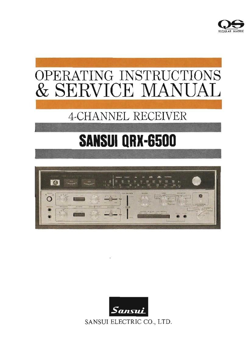
Sansui QRX 6500 Service Manual

This is the 48 pages manual for Sansui QRX 6500 Service Manual.
Read or download the pdf for free. If you want to contribute, please mail your pdfs to info@audioservicemanuals.com.

Page: 1 / 48
left right
Sansui QRX 6500 Service Manual

Extracted text from Sansui QRX 6500 Service Manual (Ocr-read)


Page 2

Congratulations on joining the thousands of proud, satisfied owners of quality
stereo components from Sansui.

The QRX-GSOO is a 280-watt 4-channel receiver endowed with practically all
the facilities necessary for enjoying every type of music in the new, enthrall-
ing 4«channel format. Incorporating the widely-acknowledged Sansui QS
REGULAR MATRIX system, it features the exclusive QS VarioeMatrix
Circuit, which (1) decodes encoded 4-channel program sources back into 4-
channel, and (Z) transforms (synthesizes) conventional 2-channel sources into
4-channel. It also has complete provisions for reproducing discrete 4-channe1
sources. And of course, it reproduces 2-channel sources in 2»channel stereo
if you so desire.

The QRX-6500 connects up to three pairs of speaker systems for the front
channels, and two pairs for the rear channels, enabling you to hear the
reproduction in two rooms. In addition, it is provided with a Synthesizer/
Decoder Function Control and a Mode Switch to let you hear each selection
with the most effective sound effect. In short, we have made it one of the
most complete, most versatile Air-channel receivers available today

Now it is up to you to read the instructions contained in this booklet, so that
you may take full advantage of its rich performance potential

Again, welcome to the world of 4-channel stereo, and our sincere gratitude
for your choice. You will not be disappointed.

CONTENTS

SWITCHES AND CONTROLS ................................................... 3~7
TO ENJOY 4-CHANNEL STEREO AT ITS BEST ........................... 8
CONNECTING SPEAKER SYSTEMS/PLAYING RECORDS ......... 9, 10
RADIO RECEPTION ............................................................ 11, 12
2-CHANNEL TAPE DECKS ................................................... 13, 14
4-CHANNEL TAPE DECK ...................................................... 15, 16
SIMPLE MAINTENANCE HINTS .......................................... 17, 18
SIMPLE MAINTENANCE HINTS/ACCESSORIES ........................ 19
SPECIFICATIONS ..................................................................... 20
GENERAL TROUBLESHOOTING CHART .............................. 21, 22
DISASSEMBLY PROCEDURE ................................................ 23, 24
TEST POINTS ........................................................................... 25
SCHEMATIC DIAGRAM OF AUDIO SECTION ........................ 26, 27
SCHEMATIC DIAGRAM OF TUNER SECTION ........................ 28, 29
ALIGNMENT ..................................................................... 30~32
PRINTED CIRCUIT BOARDS AND PARTS LIST ..................... 33~45

OTHER PARTS AND THEIR LOCATION ON CHASSIS ............ 46~48