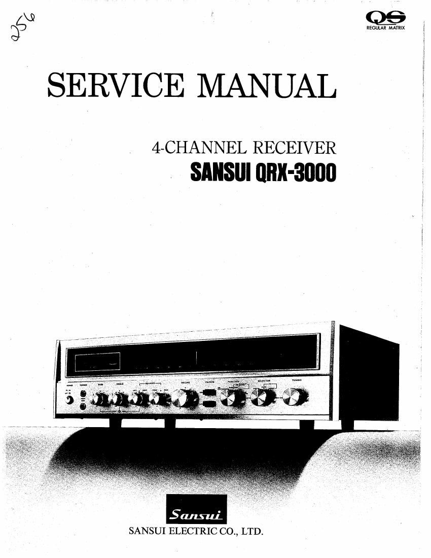
Sansui QRX 3000 Service Manual

This is the 32 pages manual for Sansui QRX 3000 Service Manual.
Read or download the pdf for free. If you want to contribute, please mail your pdfs to info@audioservicemanuals.com.

Page: 1 / 32
left right
Sansui QRX 3000 Service Manual

Extracted text from Sansui QRX 3000 Service Manual (Ocr-read)


Page 2

This service manual is designed for service engineers to repair,

adjust, maintain and order the replacement parts of the QRX-3000
correctlyt
When ordering the parts, use the stock number and parts name speci-

ficall

y referring to the Parts Locations & Parts List.

For general usage and maintenance of the unit, please refer to the
Operating Instructions attached with the unit.

TABLE OF CONTENTS

Sectio

1.
2.

10.
11.
12.

n Lte Page
SPECIFICATIONS .............................................. 3
BLOCK DIAGRAM AND LEVEL DIAGRAM .................... 4

2-1. Block Diagram .........................
2- 2. Level Diagram ...........................

ALIGNMENTS AND ADJUSTMENTS .......................... 6
3- 1 Regulated Power Supply Board Adjustment ................ 6
3 2. Driver Circuit Board Adjustment ........... ... 7
3- 3. FM lF Alignment ......................... .I 7
3- 4. FM Dial Calibration and RF Alignment .............. .. 8
3- 5, FM Meter, Mono Distortion and Muting Adjustment ........ 8
3- 6t MPX Alignment .......................................... 9'
3- -7 AM IF Dial Calibration, RF and Meter Alignment . 10
THREADING OF DIAL CORD ........................ 12
TROUBLESHOOTING CHART ........................... 12
5-1 Troubleshooting on Power Supply Section .... ..... 12
5-2. Troubleshooting on Audio Section ............... 12, 13
5-3. Troubleshooting on RF Section .......... 13, 14, 15
PARTS LOCATIONS AND PARTS LISTS ...................... 16
6-1 F-1453-3 (A) Tuner Circuit Board .................. 16, 17, 18

6-2. F-1245-1 (B) Separation and Filter Circuit Board ..
6-3. F-1267-E Equalizer Circuit Board ................
6-4. F4466 Switch Control Circuit Board ............
6~5. F-1467 High Filter Circuit Board ................


6-6. F-1465 Volume Control Circuit Board .................... 22
6-7. F4464 Tone Control Circuit Board .................. 23, 24
6- 8. F-1358C Driver Circuit Board .....

6- 9. Special Parts List ........................................ 25
6- 10. F-1469-1 Power Supply Circuit Board 26
6-11. Other Parts (Front Side) ....... . 27
6-12. Other Parts (Top Side) ....... . . 28
643. Other Parts (Bottom Side) .......................... .. 28
SCHEMATIC DIAGRAM OF TUNER SECTION ................ 29
SCHEMATIC DIAGRAM OF AUDIO SECTION ................ 30
REPLACEMENT OF MAIN PARTS .................. . 31
9-1. Dial Lamp ................................. . 31
9-2. Dial Plate ............................. . 31
9-3. Switch Assembly ....................... , 31
9-4. Volume and LOW Filter. .. .............. . 31
9-5, HIGH Filter ........................... ... 31
MAINTENANCE .............................................. 31
PACKING LIST .............................................. 31

ACCESSORY PARTS LIST .................................... 31

Page 12

QRX-aooo

4. THREADING OF DIAL CORD

lf dial cord is cut or slips, replace cord by following
procedures. As QRX-3000 has a variable capacitor-
driving mechanism using O.7mm¢ cord and a dial
pointer-driving mechanism using 0.3mm¢ cord, please
replace them with same types certainly.

* Thread the variable capacitor-driving mechanism from
1 to 9 first, then thread the dial pointer-driving mecha-
nism from 10 to 18 as Fig. 4-1.

inner pulley

\3% turns 4

I

/ ituning

shaft
2

\

Fig. 4-2

1. Variable Capacitor-Driving Mechanism

1) Close the variable capacitor completely (maximum
capacitance) and tie cord to number (9 screw of the
dial pulley.

2) Thread cord in the direction of arrow from 1 to 3.

3) Wind cord three and half times around the tuning
shaft counterclockwise and toward the TUNING
knob.

4) Thread cord in the direction of arrow from 4 to 5
and wind it on the dial pulley from 5 to 8.

5) After 8, pass cord through the spring then wind one
turn.

6) After 9, tie cord to number @ screw.

*After threading, make sure that the dial' mechanism

operates correctly by turning the TUNING knob.

2. Dial Pointer-Driving Mechanism

1) Open the variable capacitor completely (minimum
capacitance) and tie cord to the dial spring as
Fig. 4-2.

2) Fix the dial spring with screw to number on varia-
ble capacitor side of the dial pulley.

3) Thread cord in the direction of arrow from 10 to 15.

4) Thread cord from 15 to 16 and wind it on the dial
pulley from 16 to 18.

12

5) After 18, tie cord to number 62) screw.

*Make sure that the dial mechanism operates correctly
by turning the TUNING knob.

*After procedures, lock the knots of cord with paint
certainly.

3. Attachment of Dial Pointer

1) Turn the TUNING knob and
close the variable capacitor
completely (maximum capa-
citance).

2) Set the dial pointer to 0"
on dial scale and tighten the
dial pointer assy. (See Fig.
43)

*Make sure that the dial me-

chanism operates correctly by
turning the TUNING knob.

Stock No. Description
6036020 Dial Cord 0.7".qu
6036040 Dial Cord 0.3mm}
6906041 Spring G
6906091 Spring H

5. TROUBLESHOOTING CHART

571. Troubleshooting on Power Supply Section
Symptom Check Point
1. No power supplied to each section

1-1. Each lamp not lighted

1'2. Each lamp lighted

1) 41.5V not supplied to collector of TRsm (TRaag) on
F-1358C

2) 33V not supplied to collector of TRcas (TRso-l) on
F-1267

2. Wrong voltage supplied to each terminal on F-1469

11.
E12.
13

-1) Wrong voltage supplied to terminal on
F-1245-1(B)

-2) Wrong voltage supplied to emitter of TRON on
F-1469

14.
I-15

5-2. Troubleshooting on Audio Section

1. Quick acting fuse not open

1-1. +41.5V supplied to collectors on each power transistor
(TRsro, TRsos)

1) Center voltage ~l-20V not supplied----1.

1-2. +41.5V not supplied to collectors on each power

transistor (TRaxo, TRm) 2.

2. Quick acting fuse open

2-1. After replacement, fuse not open-3,
2-2. After replacement, fuse open again -4
--S
-6
-7

Cause & What to Do

'I. imperfect contact of power supply cord
2. Powerfuse Fans open

3. Imperfect contact of voltage selector

. Defective power switch so!

, Defective power transformer

. F0. on F-1469 open

. F001, F002 on F1468 open
. Defective Dam on F4469

Fog on F4469 open

~ DEfECIlVE 0002, D003 on F1469

Defective TRom, TRnae, TRooa on F1469
VRom out of adjustment on F1469

. Defective ZDW. on F-1469

Defective Dool~Daou on F-1469

. Defective TRom on F-l469

Defective TRaaa (TRBDI) 0n F'1358C

Defective power supply section

Set the bias current ZOmA (See page 7)

. Defective TRam, TR: (TRSOU, Tle) on

F-1358C

. Defective TRm, TRm (TRsm, TRaoT) on

F-1358C

. Defective D3112 (D301) on F-1358C
. Defective VR502(VR591) on F-1358C