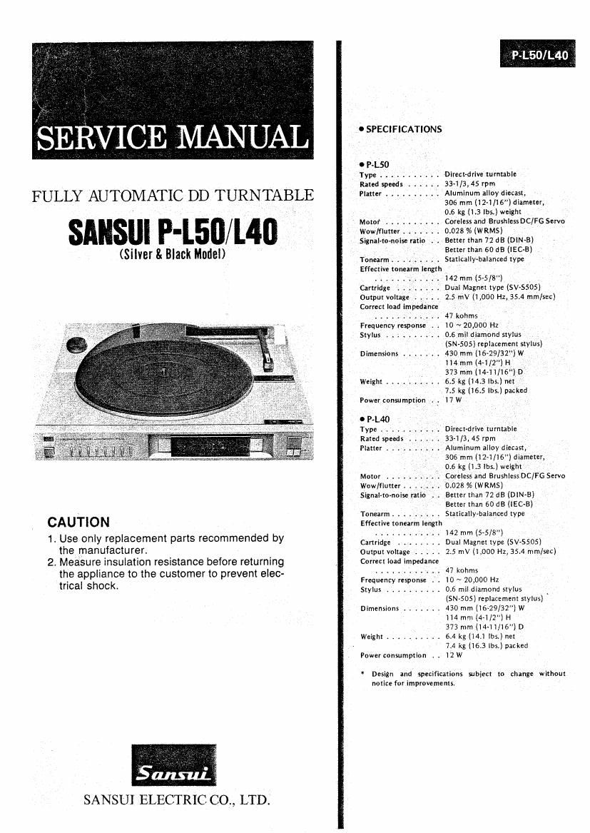
Sansui PL 50 Service Manual

This is the 24 pages manual for Sansui PL 50 Service Manual.
Read or download the pdf for free. If you want to contribute, please mail your pdfs to info@audioservicemanuals.com.

Page: 1 / 24
left right
Sansui PL 50 Service Manual

Extracted text from Sansui PL 50 Service Manual (Ocr-read)


Page 1

0 SPECIFlCATlONS

O P-L50 _
Type . . . . . . . Direetdrive turntable
Rated speeds . . . 33-i/3,45 rpm

FULLY AUTOMATIC DD TURNTABLE Platter ...... f . . . Aluminum alloydiecast,

306 mm (l2~1/l6") diameter,
0.6 kg (1.3 lbs.) weight

_ Motor .......... Careless and-Brushless DCIFG Servo
I Wow/flutter . . . . 0.028% (WRMS) '
_ .Signal-to-noise ratio ,. . Better than 72 dB (DlN-B) :

' - Better than 60 dB (lEC-E)
(Silver & Blank Model) Tonearm ....... . StaticalIy-balanced type
Effective tonearm length
, ....... . 142 mm (5-5/8") _
Cartridge . . . . . . Dual Magnet type (SV-SSOS)
Output voltage ..... 2.5 mV (1 ,000 Hz, 35.4 min/sec)
Correct load impedance _,
47kohms ,
Frequency response . . 10 ~ 20,000 Hz ,
Stylus ..... I ..... 05 mil diamond stylus
, '(SNSOS) replacement stylus)
Dimensions ....... 430 mm (16-29/32) ,W
114 mm (4-1/2") H,
373 mm (144 1/16") 0'
Weight .......... 6.5 kg (143 lbs.) net _
_ / 7.5 kg (16.5 lbs.) packed
Power consumption .'. 17 W
0 P-L40 , ,
Type . . . . Direct-drive turntable
Rated speeds . r 334/3, 45 rpm
Platter .......... Aluminum alloy diecast,

306 mm (12»1/16) diameter,
0.6 kg (1.3 lbs.) weight
Motor ; Coreless and BrushiessDC/FG Servo
Wow/flutter . . 0.028 % (WRMS)
Signal-tonoise ratio L. . Better than 72 d8 (DIN-B)
_ V Better than 60 dB (lEC-B)
Tonearm r . .' r r r ,_ . . Statieallymalanced type

CAUTION Effective tonearm length
........... t i42 mm (5»5/8")

1. Use only replacement parts recommended by Cartridge Dual Magnmype (svssos)

the manufacturer. ' . Output voltage ..... 2.5 mV (1 .000 Hz, 35.4 mmiseC)
2. Measure insulation resrstance before returning Correct load impedance

the appliance to the customer to prevent elec- ---------- . 47 W

trical ShOCk Frequency response . . 10 ~ 20,000 Hz

' Stylus .......... 0.6 mil diamond stylus
(SN-505) replacement stylus)
Dimensions ....... 430 mm (16-29/32) W

H4 mm (4-1/2") H
373 mm (i4-ii/16") D

Weight .......... 6.4 kg (14.1 lbs.) net
7.4 kg (16.3 lbs.) packed
Power consumption . . 12W

* Design ind specifications subject to change without
notice for improvements.

SANSUI ELECTRIC CO., LTD.

Page 2

3003C fitting its portion of printed ,

9- MA i_- '
' 'N PARTS REPLACEMENT
5) Bend lead-wires olfzfinstefiggal n. f ' td . mm

9-1 R
' eplice
men: . . .
of Tone Arm Dnvmg Wire l
circuit board 5-0
6) Place the new it: (H3OOBC
) and bend both outside lead (See Figs. 94,

(See F'
Is. 4.4
on Page 6,Top View On Page 14)
t on Page 7} board (5-0121
9-5)
A r

-w lres,

move
the mechaguidc

o
sen the lensio
F is. 9-4

) Lo
n mum screw.

em,
5) Tak 0: 1h: puny (B).
under the mecha-

9-2
. Rem
ace
See or $022; 3f Arm Bearing Ass'y ®
'9" of Mechanism Assy on Page 15)

(3) to remove the tone
Fig. 9-5

9-3 R
eplac
1) Re 5" 9:22? of Lifter Cam
eZOVe the . W of Mechanism Assy on Page 15)
eve th
3m e On .
two the ar e arm Ass'y ® .
Ell/Id weight 7) Solder point (5)
De Washer and s rin
9 caxtcea'npgaxe @.® ® p 3 ® 9-5. Note on Parts Replac
'4- Repla etaken out. 1) When replacing a parts of the me
) Rem Cement stylus.
ove he cab. of Hall Element (HSOOBC) 2) When an
men (See How to remove the cabinet on page 7) SM"- guide
3) Refer to Fig. 9-1, w

|
2) PL,
u on
. t he
Shaft .
w?! magnet of D.D. Motor.
(3 by soldering iron. .
4) When replacing a parts of th
gs referring to the toe vie

1 4-1, 4-2, 4-4, 4:5

or (3 (See Fig. 9.1)

ement

chanism assy, remove the

3)
, plane washer
g the worm shaft assy (B) ((5), remove the warm
and the screw
hen wirin

rtrldge (tone arm assy >
i
i

e mechanism assy, make proper

w on page 14 and Fig. 4-3 on page

3 from ca

WQe
Off
solder at F ®
2. 94 or

wirin
and 4-6, when replacing a

Frg 9 1
6.
5) Perform adjustmen
parts of the mechanism assy.

Fig. 9-6. S-OllG Circuit Board for connections between P.U. Out-
put cord & color wires from cartridge, E sensor and F sen-
sor.

P.U. Outpu Cord

Col or-wires

ir om
Cunrldge ,

blackfi
purple/-
P.Lso yellow=-:..=

rev r;

0n|y
orange fl:

:ig. 93

16

Page 15

P-L50/ L40


5-4. 50157 A, B, C Sensor L.E.D. Circuit Board 5-7. 5-0135 Voltage Control TR Circuit Board
Component Side (P'L50/L40> Component Side
4'15" ~smsw L ,- :

LED n m » - g e
+15v ' » V - m
=1 s 3 9* >
0157 -' x.» 5
0 E
Parts List
Pm; No. Stock No. Dncviption Parts List
fLD1~3 46150400 LED TLR-121 Pm N°' smd N° °"°"""°"
ITransistor
1101 03083902 230313
1102 46149301 253744
5-5. 50158 A, B, C Sensor Photo TR Circuit Board
. "C
Component Slde hlct 07183500 uPC78M05H
+ ._ 0146144200 NJM78M05A
c SANSUI
, N m' 210039 oCapacitor
_ , 11023 07214000 0047107 25V 0.0.
a c c , BU
E 0158 C
Parts List 5-8. S-Oi 36 PROGRAM Switch & Indicator
Pvt: No. Stock No. Dmriptian Component Sid, Circuit Board
0Phow Transistor SANSUI ,_1_wv__ m \
101~3 46160000 TP5605 0136 _ :1 ES
L01 to: um 1111 L ; L135 2 165, m1 ;
1 I 1 l 1 1 I , 1 1 1 1
5-6. S-0134 Power Supply Circuit Board
Component Side
:1 4 5 a 1 9 10 11 12 1a \ *
. , s s 1 50
Ll NI J I 5 5: 53 1110510410121; 6 - s
», _ . aw: BtUE eucx RED m1 2
a _
-- Parts List
Pam Nu. Stock No. Dascription
c. gLD1~7 07250900 LED TLC-123
-11-
' gsw1~8 46395900 Push swv, RANDOM ACCESS
41 came: PROGRAM
- WWYE
. 5-9. S-0137 Control Switch & Indicator
_ ;, Camponemsm Circuit Board
, N SANSUI 0137 H mmcnomg)
R 9 E Mi urconmot -bs
» m 1. _ m
,, g u 025 447m mm A?
_ 1: E .mp-
1 1 -6»
3 C126
POWER SUPPLY 1h)
SANSUI 0134
Parts List
Parts List Pm: No. Stack Nu. Dncrinion
le No. Stock Not Dneriplion oTransmor
micde f025,26 07194801 zsc1615
0103059501 250945
0"2 03117000 "5'152 0r07299701 2502603
.2511" 010.39 1027 07194701 2541015
11021.2 40104500 05216~X or07197001 25A733
0107299601 28Ai115
oHesusmr
hR1,2 46230200 1m 1/2w N.|.R. 1025 07213600 002211F 25v cc.
lCapacnor
hc1 46425800 0.01uF 400V CC. to be continuedb
hC6.7 07213200 0.01uF 25v c.c.

11

A 42 4ha _W.,M

5 2 WW-.. .., .mvwmmwm