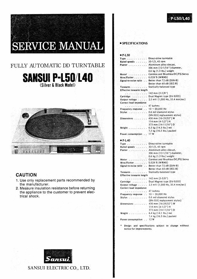
Sansui PL 40 Service Manual

This is the 24 pages manual for Sansui PL 40 Service Manual.
Read or download the pdf for free. If you want to contribute, please mail your pdfs to info@audioservicemanuals.com.

Page: 1 / 24
left right
Sansui PL 40 Service Manual

Extracted text from Sansui PL 40 Service Manual (Ocr-read)


Page 1

0 SPECIFlCATlONS

O P-L50 _
Type . . . . . . . Direetdrive turntable
Rated speeds . . . 33-i/3,45 rpm

FULLY AUTOMATIC DD TURNTABLE Platter ...... f . . . Aluminum alloydiecast,

306 mm (l2~1/l6") diameter,
0.6 kg (1.3 lbs.) weight

_ Motor .......... Careless and-Brushless DCIFG Servo
I Wow/flutter . . . . 0.028% (WRMS) '
_ .Signal-to-noise ratio ,. . Better than 72 dB (DlN-B) :

' - Better than 60 dB (lEC-E)
(Silver & Blank Model) Tonearm ....... . StaticalIy-balanced type
Effective tonearm length
, ....... . 142 mm (5-5/8") _
Cartridge . . . . . . Dual Magnet type (SV-SSOS)
Output voltage ..... 2.5 mV (1 ,000 Hz, 35.4 min/sec)
Correct load impedance _,
47kohms ,
Frequency response . . 10 ~ 20,000 Hz ,
Stylus ..... I ..... 05 mil diamond stylus
, '(SNSOS) replacement stylus)
Dimensions ....... 430 mm (16-29/32) ,W
114 mm (4-1/2") H,
373 mm (144 1/16") 0'
Weight .......... 6.5 kg (143 lbs.) net _
_ / 7.5 kg (16.5 lbs.) packed
Power consumption .'. 17 W
0 P-L40 , ,
Type . . . . Direct-drive turntable
Rated speeds . r 334/3, 45 rpm
Platter .......... Aluminum alloy diecast,

306 mm (12»1/16) diameter,
0.6 kg (1.3 lbs.) weight
Motor ; Coreless and BrushiessDC/FG Servo
Wow/flutter . . 0.028 % (WRMS)
Signal-tonoise ratio L. . Better than 72 d8 (DIN-B)
_ V Better than 60 dB (lEC-B)
Tonearm r . .' r r r ,_ . . Statieallymalanced type

CAUTION Effective tonearm length
........... t i42 mm (5»5/8")

1. Use only replacement parts recommended by Cartridge Dual Magnmype (svssos)

the manufacturer. ' . Output voltage ..... 2.5 mV (1 .000 Hz, 35.4 mmiseC)
2. Measure insulation resrstance before returning Correct load impedance

the appliance to the customer to prevent elec- ---------- . 47 W

trical ShOCk Frequency response . . 10 ~ 20,000 Hz

' Stylus .......... 0.6 mil diamond stylus
(SN-505) replacement stylus)
Dimensions ....... 430 mm (16-29/32) W

H4 mm (4-1/2") H
373 mm (i4-ii/16") D

Weight .......... 6.4 kg (14.1 lbs.) net
7.4 kg (16.3 lbs.) packed
Power consumption . . 12W

* Design ind specifications subject to change without
notice for improvements.

SANSUI ELECTRIC CO., LTD.

Page 2

3003C fitting its portion of printed ,

9- MA i_- '
' 'N PARTS REPLACEMENT
5) Bend lead-wires olfzfinstefiggal n. f ' td . mm

9-1 R
' eplice
men: . . .
of Tone Arm Dnvmg Wire l
circuit board 5-0
6) Place the new it: (H3OOBC
) and bend both outside lead (See Figs. 94,

(See F'
Is. 4.4
on Page 6,Top View On Page 14)
t on Page 7} board (5-0121
9-5)
A r

-w lres,

move
the mechaguidc

o
sen the lensio
F is. 9-4

) Lo
n mum screw.

em,
5) Tak 0: 1h: puny (B).
under the mecha-

9-2
. Rem
ace
See or $022; 3f Arm Bearing Ass'y ®
'9" of Mechanism Assy on Page 15)

(3) to remove the tone
Fig. 9-5

9-3 R
eplac
1) Re 5" 9:22? of Lifter Cam
eZOVe the . W of Mechanism Assy on Page 15)
eve th
3m e On .
two the ar e arm Ass'y ® .
Ell/Id weight 7) Solder point (5)
De Washer and s rin
9 caxtcea'npgaxe @.® ® p 3 ® 9-5. Note on Parts Replac
'4- Repla etaken out. 1) When replacing a parts of the me
) Rem Cement stylus.
ove he cab. of Hall Element (HSOOBC) 2) When an
men (See How to remove the cabinet on page 7) SM"- guide
3) Refer to Fig. 9-1, w

|
2) PL,
u on
. t he
Shaft .
w?! magnet of D.D. Motor.
(3 by soldering iron. .
4) When replacing a parts of th
gs referring to the toe vie

1 4-1, 4-2, 4-4, 4:5

or (3 (See Fig. 9.1)

ement

chanism assy, remove the

3)
, plane washer
g the worm shaft assy (B) ((5), remove the warm
and the screw
hen wirin

rtrldge (tone arm assy >
i
i

e mechanism assy, make proper

w on page 14 and Fig. 4-3 on page

3 from ca

WQe
Off
solder at F ®
2. 94 or

wirin
and 4-6, when replacing a

Frg 9 1
6.
5) Perform adjustmen
parts of the mechanism assy.

Fig. 9-6. S-OllG Circuit Board for connections between P.U. Out-
put cord & color wires from cartridge, E sensor and F sen-
sor.

P.U. Outpu Cord

Col or-wires

ir om
Cunrldge ,

blackfi
purple/-
P.Lso yellow=-:..=

rev r;

0n|y
orange fl:

:ig. 93

16