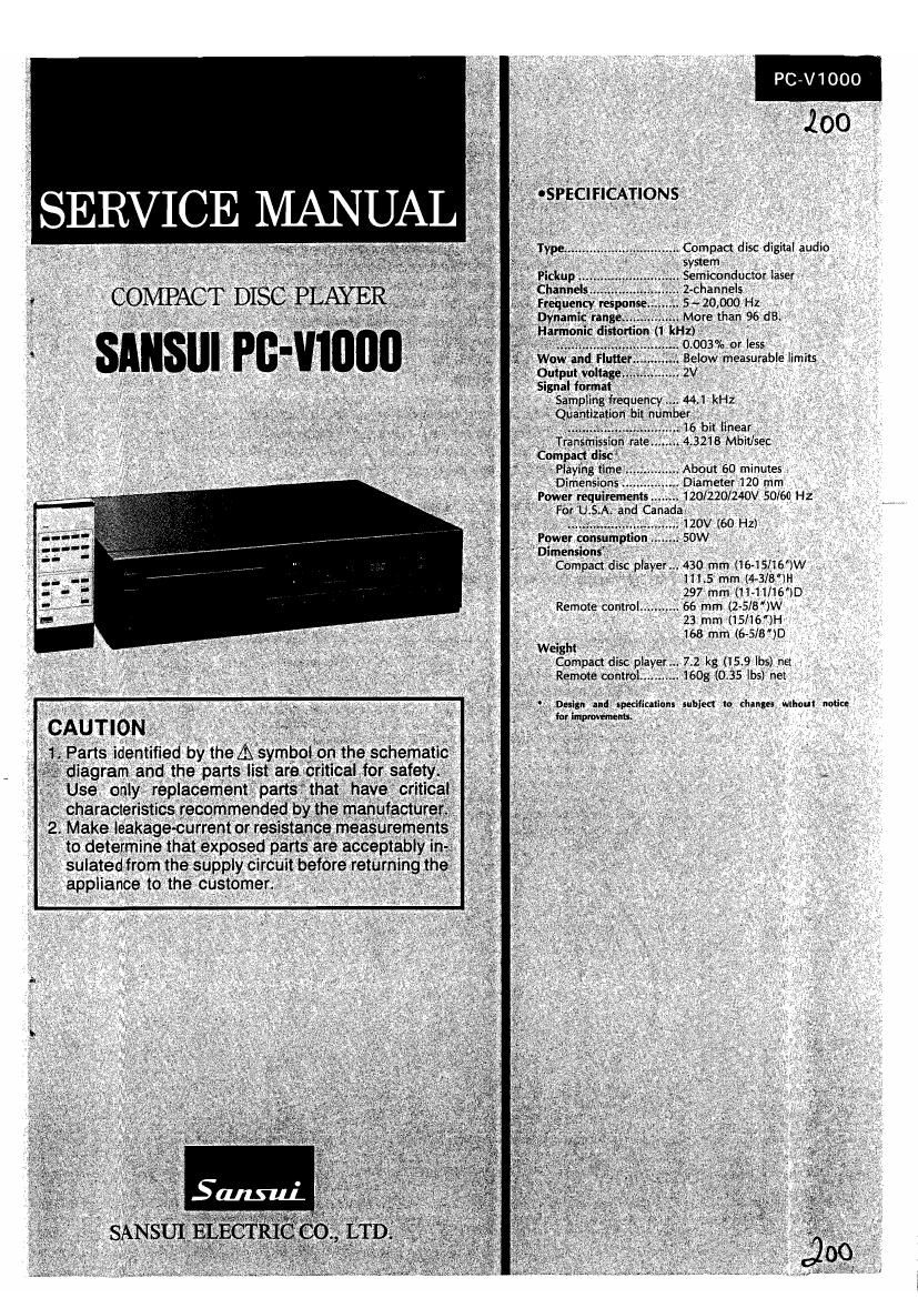
Sansui PC V1000 Service Manual

This is the 24 pages manual for Sansui PC V1000 Service Manual.
Read or download the pdf for free. If you want to contribute, please mail your pdfs to info@audioservicemanuals.com.

Page: 1 / 24
left right
Sansui PC V1000 Service Manual

Extracted text from Sansui PC V1000 Service Manual (Ocr-read)


Page 2

CAUTION

1. The symbols, LIL, CSA, BS, UK, EU, AS and XX on the parts list and

the schematic diagram mean followings respectively.

UL ....................... Manufactured for U.S.A market.
(Underwriters Laboratories approved model.)

CSA.... .. Manufactured for Canadian market.

SA. .. Manufactured for South African market.
BS, UK .. .. Manufactured for United Kingdom market.
EU ......... .. Manufactured for European market.

AS.... .. Manufactured for Australian market.

XX.... .. Standard Version.
NON MARK ........ Common Parts.

. Some printed circuit boards are not supplied as the assembled.
To separate these in this service manual, the stock Nos are not in-
dicated at the ends of the board names. However, the individual parts
on the circuit boards are provided by orders.

. Since some of capacitors and resistors are omitted from parts lists
in this service manual, refer to the Common Parts List for capacitors
& resistors, which was issued on February 1983.

. Abbreviations in this service manual are as follows.

OAbbreviations List

C.R. : Carbon Resistor E.B. : Bi-Polar Electrolytic

S.R. : Solid Resistor Capacitor

Ce.R. : Cement Resistor E.B.L. : Low Leak Bi-Polar

M.R. : Metal Film Resistor Electrolytic Capacitor

F.R, : Fusing Resistor Ta.C. : Tantalum Capacitor

N.I.R, : Non-Inflammable Resistor F.C. : Film Capacitor

A.R. : Array Resistor MP. : Metalized Paper Capacitor

C.C. : Ceramic Capacitor P.C, : Polystyrene Capacitor

C.T. : Ceramic Capacitor, C.C. : Gimmic Capacitor
Temoerature Compensation A.C. : Array Capacitor

E.C. : Electrolytic Capacitor V.R. : Variable Resistor

E.L. : Low Leak Electrolytic S.V.R, : Semi Variable Resistor
Capacitor SW. 1 Switch

Page 21

PC»V1000

PC»V1000

Adjustmenl procedur-

Cllocltud Position

Adjumd Pam

Adjustment Cum-nu

Adjusting Conditions

W7

AdjuitlnInt procedur-

Chcckld Posltion

Adjusted Pam

Adjullmont Comm

Adjusting Condition;

Check of feed
output

Between E
point and
ground (Emitter

0 Check that waveform is as shown be-
low with GAIN terminal set to H(5V)
or Llchassis).

The same as described under Procedure
15 above.


focus loop is
not out of the
normal condi»
tion.

of P07) (GAIN terminal ..... L>
Oscilloscope About 15v About 2v
-r ~1-
7%QYIABSV' Again
KOSC wavetorm 4
o If tracking gain is excessive, oscilla-
tion begins when GAIN terminal is set
to H.

18 Adjustment of Between F EVRI oAdjust duty ratio to 50 percent as 1. Return connectors CO1, C02, C03,
main motor revo» point and shown below. CO4 C05 and C06 on board 5-2011
lution. ground (an in- Wavelnrmat r burnt and C07 on board 5-2006 to the

tersection of Wavelcrrnm rrlrorma) n original state before adjustment.
enzo and ER1) Eggnrwtéml °'"""° °"""" " 2. Operate the set in PLAY after MUSIC
Oscilloscope 99'"? 3W"" SELECT has been completed.

-i Li Li i-i L Leadlng phase drnerehce

19 Check of per» PVR5 Fifteen musics must be reproduced. If The same as described under Procedure
formance not reproduced, adjust tracking gain 18 above.
1. Check that no finely.

sound jump
occurs by the
use of a Philips
TEST SAMPLE
DISC (NR 4A
410-0564).
2. Check that PVR3 Perform start operation after loading

open. Repeat this operation two or
three times. In this case, music must
be reproduced smoothly, If not
smoothly, adjust focus gain finely,

1O Adjustment of Between D Eccentric 0 Adjust eye patern at the best 1. POWER ..... ON 2. Disc ..... set
mechanism section point and_ cam in _ condition. 3. MAI?) MOTOR ..... ON (by applying
W W 33331: 23 V a 4 33.. 3.333.325.3333: gnaw

5 \ i'i'i't'i't't'iVW'i'i'V'i't'i *r 5' LASER ' I Ll h "-"i
OsCIlloscope g _ i 6. iti 7 g . termlna ..... c assls
Front Sectlon of Disc Table 1 i. V V I. 6' PLAY terminal ' Mohass's)
< "...AA. 3". < 7. Move head base (feed) to the center
* \YAYA Azuzaasmrum. of the disc in accordance with the
The best condrtrorr obtalnsd whe bbroprrate following method:
Drees Panel Eccentric Cam openlngs exist on both the upper and lower Sides oApply 5V to the connector C03 on
board Sr2011 as shown in Fig. 1.
(Connect the adjusting connector lead
'Remove Dress Panel assembly TC3 as depicted below.)
I p' T bl
mm '56 a e . ..Wavefnrn1 at FEED MOTOR
, T imam... SQ):
W Pom eye Tc3
W" H i i i i i i i i i i m Moves outwards
a 2903ng degree It mm
.aw... 3333:3335 _ 3:i°.':9 W 5. $20
Correct data are not read .EZIHMHI at normal rcvolutlcn TCS
Note: In case eye pattern will not be improved under this adjustment, return to Ad- Rea Moves lnwards
justment Procedure 7, because the two maximum waveform amplitudes are 5v
rever sely adjusted at the normal and abnormal points in adjusting diffract» Slack
ing grating. (ERTH)

11 Adjustment of Between D PVR2 oAdjust eye pattern at the best The same as described under Procedure

focus offset point and condition 10 above.
ground (pin 23
of PlCil
Oscilloscope

12 Fine adjustment of B point (pin 28 PVRG 1 ~'~'-'~'- -~,~,-,~'-'~~'-,- * 1. POWER ..... ON 2. Disc ..... set
tracking mirror of P_|C1) > Wfiifiii;§v§i§z§i§. g 3. MAIN MOTOR ..... ON (by applying
preset result Oscilloscope. g A _ Q§QH¢¢. iiiiiiii 7 a 4 35% to anEXJBr/Igstshovvnl ln Flgl-Iilfiw

1 N . an ermlna s .....
Between 0 < {39243929292929 2924;25292492 < 5. LASER terminal . Llchassis)
3° and . n. r... 3...... 3- EU" termlng' ----- 5 . . f
g;c;ag)(EmItter openlngsexlst on both the upper and rows, spas - P5322231). eencurtreglé ggiltlm a
0 59 O -
DC voltmeter 0 Check that voltage lies within abO.3V (Return to the current position after
at 0 point. Procedure 14.)
13 Fine adjustment of Between C Screw on The same as described under Procedure
diffraction grating point and head lower at 12 above.
ground (an in- side (See (7 -g
tersection of Fig.3 on ; 2g
PR50 and page 21) > "
PR51) x
Oscilloscope
14 Fine adjustment of Between C PVR4 The same as described under Procedure
tracking offset point and 12 above.
ground (an in- a
tersection of b
PRSO and
PR51) ashould be equal tap
Oscilloscope

15 Check oieve pat- Between D oCheck that eye pattern is in the best POWER ..... ON 2. Disc ..... set

tern when head is point and condition when head base (feed) is MAIN MOTOR ..... ON (by applying

move to the inner
and outercircum»
frences of a disk.

ground (pin 23
of PIC1)
Oscilloscope
DC voltmeter

moved to the inner and outer circum-
ferences. Refer to Procedure 10 with
respect to the method of moving
head base.)

oCheck that voltage is L(0Vl at Focus
terminal while head base is being
moved.

3.5V to motor as shown in Fig. 1)
GAIN and LAMP terminals ..... H(5Vl
LASER and PLAY terminals

..... Llchassis)

Return PVR5 to the position remem-
bered under Procedure 12.

.05"? 97

16

Check of switching
operation of track-
ing loop

Between 0
point and
ground (Emitter
of P05)
Oscilloscope

oCheck that waveform is as shown be-
low with GAIN terminal set to H(5Vl
or Llchassis).

IlllliliiiiiimMilli)

Tracking dnve srpnal lncludlng
hrgh (reduencv hand corncorrehts
Mrrror preset value

[The level . changes accordrhg
to setting method)

The same as described under Procedure
1 5 above.

(GAIN terminal ..... L>

Mrrrpr preset value

ngh lrequencv band corn orients are reduced and
low (tendency band wave prrn Is nptarhed due to
eccenlrlclty

12-2. Adjustment of electric circuits other than Mechanism Servo Section

Adjustment Procedure Checked Position Adjusted Plnl Adiuttnt-nt Contents Adjusting condition.
1 Rough adjustment Between G qL1 4.3128MH2 1. Check that the connectors of board
of bit PLL point and ($2007) 5-2011 are all connected correctly.
ground (Pin See Parts 2. Disc ..... none 1
22 of qlC1) Location 3. POWER ..... 0N l
Frequency F-2007 on
counter Page 18
See Parts Lo»
cation F-2007
on Page 18
2 Adjustment of Between F eVR1 Adjust duty ratio to 50 percent as 1. POWER ..... ON
main motor point and shown below. 2. Operate the set in PLAY after MUSIC
revolution ground (an Waveform at r point SELECT has been completed,
intersection of Waveform .h normal
eRZO and Dwvraw 50%. revolullohicurrecl adjustment)
eR1) 7° 7 5 taggrhc phase drnsrence
Oscilloscope
)_lLl L tsacrna phase cratershce
3 Fine adjustment of Between qL1 Adjust error within 2ms. 1. POWER ..... 0N
bit PLL TPC1 and See Parts Em, Em, Em, Em), 2. Reproduce the fifteenth music on
ground Location Philips TEST SAMPLE DISC (NR4A
(5-2006) (See F-2007 on 410-0564).
Fig. 1) Page 18 3. Set TIME/DIV to 1ms and TRIG
Oscilloscope MODE to NORMAL. VOLTS/DIV to AC,
COUPLING to AC in oscilloscope.
Adjust this portion within'2ms, where
there is no signal cause of black spot.
In case it is impossible to adjust it
within 2ms, finelv adjust pVROS and
pVR02 while watching eye pattern.
4 Adjustment of OUTPUT qVR1 Match the output level of L-CH to that 1. POWER ..... ON
level difference terminal, See Parts of R-CH (about 2V). The variable range 2. Reproduce the first music on SONY
between L-CH and Oscilloscope Location of pVR1 is within a: 1dB TEST DISC (TYPE 3 YEDS7).
R-CH F-2008 on Therefore, in case of no TEST DISCr
Page 15 set qVR1 at the center.

24