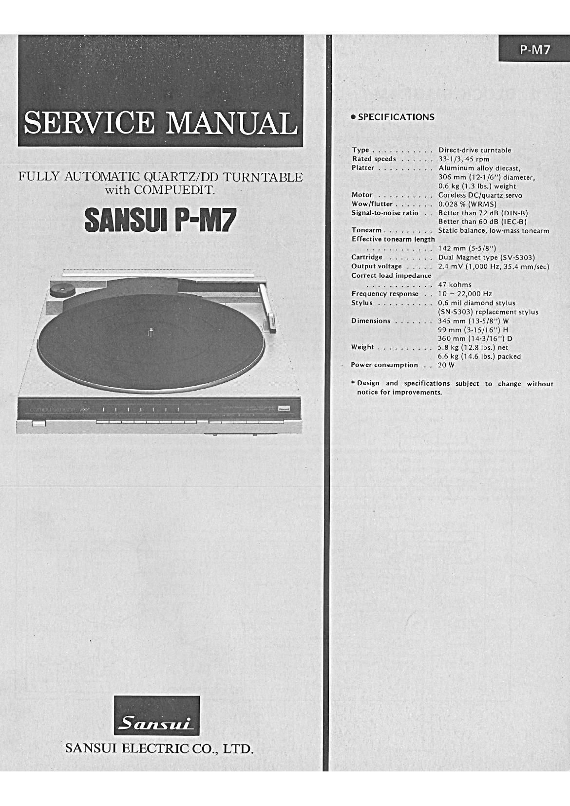
Sansui P M7 Service Manual

This is the 16 pages manual for Sansui P M7 Service Manual.
Read or download the pdf for free. If you want to contribute, please mail your pdfs to info@audioservicemanuals.com.

Page: 1 / 16
left right
Sansui P M7 Service Manual

Extracted text from Sansui P M7 Service Manual (Ocr-read)


Page 1

FULLY AUTOMATIC QUARTZ/ DD TURNTABLE
with COMPUEDIT.

SANSUI P-M7

I SANSUI ELECTRIC CO., LTD.

0 SPECIFICATIONS

Type ...........
Rated speeds ......
Platter ..........

Motor ..........
Wow/flutter .......
Signal-to-noise ratio . .

Tonearm .........
Effective tonearm length
Cartridge ........
Output voltage .....
Correct load impedance
Frequency response . .
Stylus ..........

Dimensions .......

Weight ..........

Power consumption

Direct-drive turntable

33-1/3, 45 rpm

Aluminum alloy diecast,

306 mm (12-1 /6) diameter,

0.6 kg (1.3 lbs.) weight

Coreless DC/quartz servo

0.028 % (W RMS)

Better than 72 dB (DIN-B)
Better than 60 dB (lEC-B)
Static balance, low-mass tonearm

142 mm (5-5/3")
Dual Magnet type (SV-5303)
2.4 mV (1,000 Hz, 35.4 mm/sec)

47 kohms

10 ~ 22,000 Hz

0.6 mil diamond stylus
(SN-S303) replacement stylus
345 mm (13-5/8") w

99 mm (3-15/16) H

360 mm (14-3/16") D

5.8 kg (12.8 lbs.) net

6.6 kg (14.6 lbs.) packed

20 W

*Design and specifications subject to change without
notice for improvements.

Page 8

P-M7

D. Delay adjustment of E2 signal

1. Setting

Use the record disk in which many musics (about seven music

tracks) are recorded, and select three music tracks having lead-over

grooves, respectively, near positions 70mm, 100mm, and 130mm

away from the disc center.

2. Adjustment (See Fig. 3-5, Top View on Page 8)

Perform the respective lead-in operations for three selected music

tracks, and adjust the operations by rotating the volume (fVR4) as

shown in Fig. 3-3 so that the stylus comes down on or a little before

the lead-over grooves for the three music tracks. If the volume

(fVR4) is rotated clockwise, the lift-down position of the stylus is

shifted inward.

Note: In the lead-over grooves existing on a 70mm-or-less from the
center, the misplacing of the arm in detection position occurs
inevitably.

Fig. 3-5 Cartridge

L 5' :3 Disc

' 7,6 5'432.1 \l
7cm-oi

1 0cm

13cm

Note: Remove the cabinet before adjustments of 3-3 and 3-4.

0 How to remove the cabinet. (See Top View .on Page 8)

1) Unscrew seven cabinet-mounting screws on the bottom of the
chassis.

2) Remove the E-ring fixing the turntable to the spindle of the
motor.

3) Remove the player case cover.

4) Move the tone arm to the player case cover position by depress-
ing the MANUAL key ( 4 ), before removing the cabinet.

3-3. Arm Servo Adjustment (See Fig. 3-4, Fig. 3-5)

A. Setting

1) Move the tone arm leftward and stop it within the record-play-
able range by depressing the MANUAL key ( V ).

2) Move the tone arm downward by depressing the UP/DOWN key.

B. Adjustment

1) Loosen the sensor holder fastening bolt, and adjust the arm servo
adjusting cam so that the tone arm does not move in either direc-
tion, in the state where the tone arm is in the down position.

2) After adjustment, check that the voltage across the connector
terminals No. 9 or TP6 and GND of S-0107 (across the terminals
of the micromotor (I) is within 0V 11V when the sensor holder
fastening hexagon bolt is fastened.

3) Check that the tone arm will not move in either direction when
the UP/DOWN key is depressed repeatedly.

Fig. 3-6 Arm Servo Adjusting Cam

Sensor Holder
Fastening Bolt

3-4. Tension Adjustment of Tone Arm
Horizontally Driving Wire (See Fig. 3-4)

Move the tone arm by depressing the MANUAL key and adjust the

tension adjusting screw so that the wire does not slip along the driv-

ing gear.

Note: Care must be taken not to fasten the tension adjusting screw
too tightly.

0 Variable resistors in the DD motor control circuit 7

The variable resistors (eVR1, eVR2 and eVR3) in the DD motor
control circuit are used for adjusting wow and flutter. These variable
resistors have already been adjusted accurately before shipped, be-
cause a special measuring instrument is required for adjustment.
Therefore, when the motor is required to be replaced by a new one
because of irreqular rotation, replace the motor assembly and all
(Stock No. 18022201).

4. 0TH ER PARTS

Parts List

Parts No. Stock No. Description

1 18026401 Tone Arm Assy with Cartridge
SV»S303

2 131 10600 Stylus, SN<8303

3 13103900 Arm Fiest

4 13105000 Control Plate

5 18025401 Push Knob Ass'y (1)

5-1 Mounting Plate, push knob

5-2 13099700 Push Knob, START/STOP

5-3 13099800 Push Knob, MANUAL, UP/

DOWN, REPEAT

6 13100000 Slide Knob. SPEED,
SENSITIVITY

7 18025501 Push Knob Ass'y (2)

7-1 Mounting Plate, push knob

7-2 13099800 Push Knob, CLEAR, music

selection 1 ~ 7

8 13099900 Push Knob, POWER

8-1 Knob Holder

9 13099210 Turntable Platter
10 13099110 Turntable Sheet
11 13012300 EP Adaptor
12 131 12000 Dust Cover Assy
13 13113600 Side Hinge (L)
14 13113700 Side Hinge (F1)
15 13113800 Hinge Cap
16 13115100 Screw.M2.6x8

13097300 Insulator

Note: Parts without Stock Nos. are not supplied even parts
names are listed in the parts list.

Parts List

Parts No. Stock No. Description

1 38004700 Power Supply Cord

2 39106000 Strain Relief

3 13062500 Output Cord

4 39105700 Strain Relief

5 46170400 Jack. computer editing

6 1309791 0 Wire

7 13097400 Pipe (8)

8 13098300 Pulley (B)

9 13106000 Pipe (L)
10 13106200 Pipe Holder
11 18022201 SSD-l DD Motor Ass'y with

control circuit board $0097

12 15005801 Power Transformer

07204700 Slide Switch, voltage selector