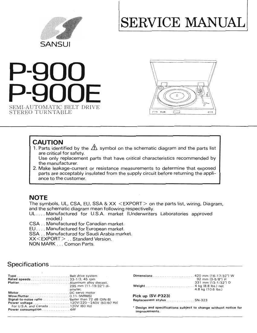
Sansui P 900E Service Manual

This is the 9 pages manual for Sansui P 900E Service Manual.
Read or download the pdf for free. If you want to contribute, please mail your pdfs to info@audioservicemanuals.com.

Page: 1 / 9
left right
Sansui P 900E Service Manual

Extracted text from Sansui P 900E Service Manual (Ocr-read)


Page 1

.SERVICE MANUAL

SANSUI

P-QDO
P-QOOE

SEMLAUTOMATIC BELT DRIVE
STEREO TURNTABLE

CAUTION

1. Parts identified by the A symbol on the schematic diagram and the parts list
are critical for safety.
Use only replacement parts that have critical characteristics recommended by
the manufacturer.

2. Make leakage-current or resistance measurements to determine that exposed
parts are acceptably insulated from the supply circuit before returning the appli-
ance to the customer.

NOTE

The symbols, UL, CSA, EU, SSA & XX on the parts list, wiring, Diagram,

and the schematic diagram mean following respectivelly.

UL. . . . Manufactured for USA. market (Underwriters Laboratories approved
model.)

CSA . . Manufactured for Canadian market.

EU. . . . Manufactured for European market.

SSA . . Manufactured for Saudi Arabia market.

XX . . Standard Version.

NON MARK . _ . Comon Parts.

Specnfications

Type .......................... . Belt drive system Dimensions ................... .420 mm (16-17/32l W

Rated speeds ...... ..33-1/3, 45 rpm 92 mm (3-5/8) H

Platter ................ Aluminum alloy diecast, 331 mm (13~1/32) D
296 mm (11-19/32) di- Weight ........................ 4 kg (8.8 lbs.) net
ameter, 4.8 kg (10.6 lbs.)

Motor .DC servo motor

Wow/flutter.

Signal-to-noise ratio . . .

Power voltage

Power consumption. , .

For U.S.A. and Canada. ........

..o.1% (WRMS)

.. Better than 72 dB (DINeB)

.. 120V/220N24OV (50/60 HZ)
..120V(60 HZ)

4W

Pick up (SV-P323)

Replacement stylus .............

.. SN-323

Design and specifications subject to change without notice for

improvements.

Page 2

P-900/900E

1. ADJUSTMENT INSTRUCTIONS

1. Auto return range adjustment
(1) If tone arm returns too early or does not return at all, adjust the auto return point in the hole located
at the right side of tone arm as follows.
(2) Lock tone arm to the arm rest and turn adj cam to counterclockwrse.
Auto return point will be later or earlier.

The stylus auto return position at 3mm pitch disk is
4.517 - 4.205 (114.74- 106.82mml from the Center shaft.


Screwdriver

Cabinet


Cabinet

Adjust Cam

Feed Arm
Fig. 1

2. Pick-up height adjustment

Tone arm actuates AUTOMATIC RETURN at the end of record.

The distance between pickup stylus and surface of single record in the arm return mode is typically 0.2704
(510mm).

Adjustment of this elevation is accomplished by means of cam adjust screw. (see Fig.2).

' ' in. Carn Adjust Screw
,

\)

Fig. 2
Note: When a cartridge is replaced, adjust the stylus tip height as the same manner.

For 3371/3 rpm In 50 H2 areas
For 45 rpm in 50 HZ areas

3. Speed adjustment

1. Adjust the pitch control knob so-that strobodots
look like stopped.

(1) + Direction control
When rotation speed is slow, turn the pitch
control knob to the left.

(2) iDirection control IF BARS DRIFT IN IF BARS DRIFI' lN
When rotation speed is fast, turn the pitch 5 D'RECT'ON I I 5 D'RECT'ON

. SPEED Is TOO FAST SPEED IS TOO SLOW
control knob to the right. .
Fig. 3
2. Pitch control range adjustment . .
(1) Set pitch control knob to its mechanical center. 0 45mm 33mm
(2) Select required speed. _A+ _n+
(3) Adjust semifixed resistor with small minus 0 . v32
VR1

driver until strobodots looks like stopped.lsee
Fig .4)
(4) Repeat for second speed. ,
1 . Fig. 4