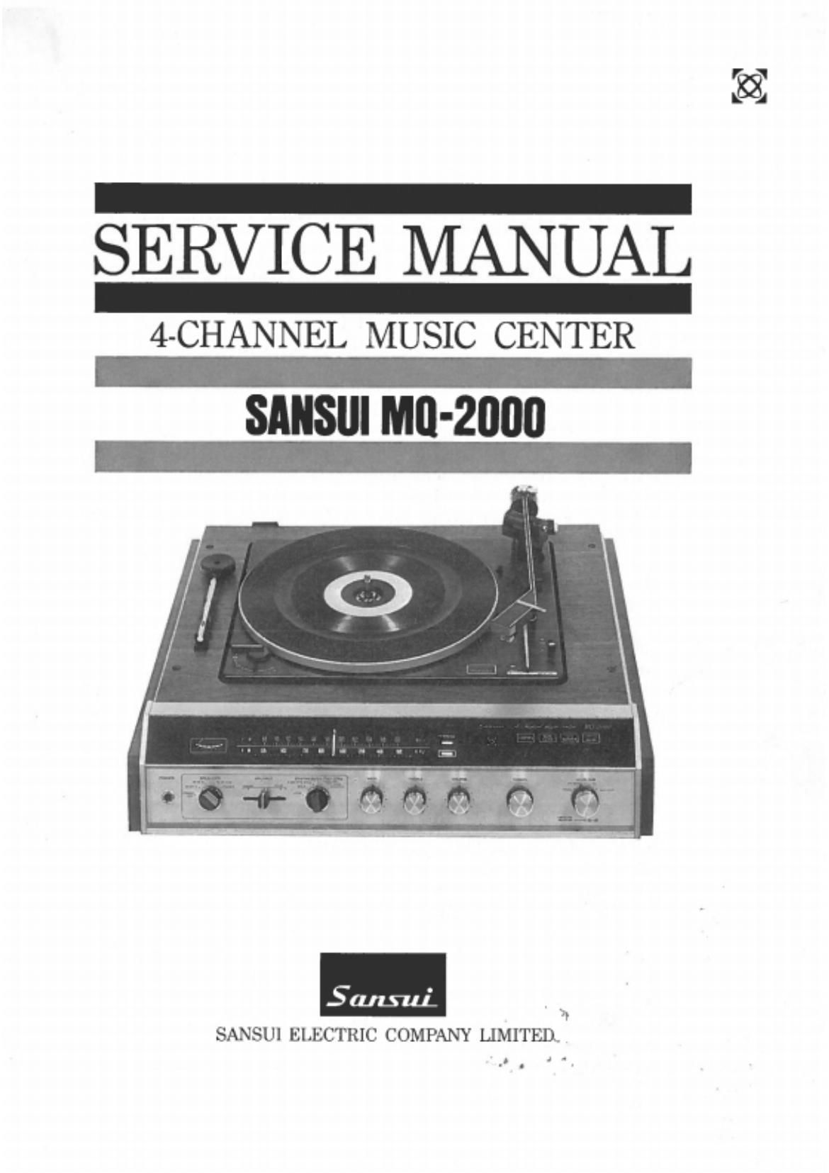
Sansui MQ 2000 Service Manual

This is the 27 pages manual for Sansui MQ 2000 Service Manual.
Read or download the pdf for free. If you want to contribute, please mail your pdfs to info@audioservicemanuals.com.

Page: 1 / 27
left right
Sansui MQ 2000 Service Manual

Extracted text from Sansui MQ 2000 Service Manual (Ocr-read)


Page 2

Dear Service Engineer:

Thank you for the trouble you are taking to service our
MQ-ZOOO.

The MQ-2000 4-Channel Music Center is designed for people
who want to enter the world of 4~channel stereo without much fuss
and without making too big an investment. Like other quality 4-
channel stereo equipment from Sansui, it incorporates our unique
QS synthesizer,'decoder circuit. It is this circuit that enables this
compact music center to rec0ver the original four channels of
signal from 2-channel program sources encoded from four channels
by a Sansui QS encoder. Equally important. it is this circuit that
enables the music center to produce exciting 4-channel stereo sound
from today's 2-channel stereo sources. by the simple changeover
of its SynthesizerfDecoder Function Control.

The matrixing or coding system of 4-channel stereo offers
these and several other advantages. Since the Sansui QS synthesizer]
decoder circuit empIOys a quite universal decoding matrix. once
you understand its design and function. you would most likely find
it easy to service matrixing system 4-channel equipment of other
makes as well.

It is our sincere hope that this manual, along with the Service
Manual for the automatic changer. provides you with all the de-
tailed iniormation required to maintain and service the MQ-ZOOO.

CONTENTS

SWITCHES AND CONTROLS .......................................... 2
GENERAL TROUBLESHOOTING CHART ..................... 3, 4
TIDBITS ..................................................................... 5. 6
BEFORE YOU BEGIN SERVICING ................................. 7
DISASSEMBLY PROCEDURE/DIAL MECHANISM ............ 8
ALIGNMENT ................................................ 9, 10. 11. 12
SCHEMATIC DIAGRAM .......................................... 13, 14
SPECIFICATIONS ......................................................... 15
PRINTED CIRCUIT BOARDS AND

PARTS LIST ........................ 16. I7. 18, 19, 20, 21, 22, 23, 24

OTHER PARTS AND THEIR POSITIONS