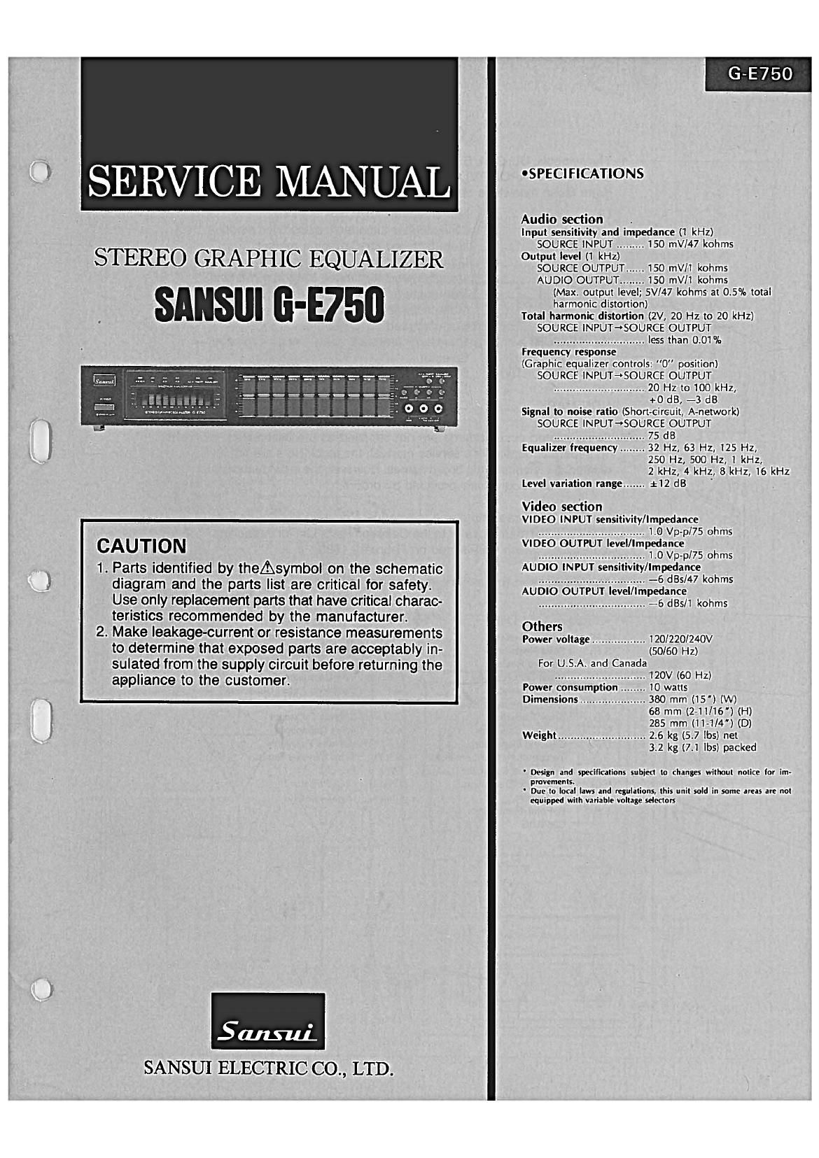
Sansui G E750 Service Manual

This is the 12 pages manual for Sansui G E750 Service Manual.
Read or download the pdf for free. If you want to contribute, please mail your pdfs to info@audioservicemanuals.com.

Page: 1 / 12
left right
Sansui G E750 Service Manual

Extracted text from Sansui G E750 Service Manual (Ocr-read)


Page 1

G-E750

OSPECIFICATIONS

SERVICE MANUAL

Audio section .
Input sensitivity and impedance (1 kHz)
SOURCE INPUT ......... 150 mV/47 kohms
l STEREO GRAPHIC EQUALIZER ou;%bl§é-‚¬Â£UT:3T....n 150 mV/l kohms
AUDIO OUTPUT ........ 150 mV/1 kohms

(Max. output level; 5Vl47 kohms at 0.5% total
. I harmonic distortion)
1 _ Total harmonic distortion (2V, 20 Hz to 20 kHz)

SOURCE INPUT-*SOURCE OUTPUT
l ............................. less than 0.01%
l ' Frequency response
(Graphic equalizer controls: "0 position)
SOURCE INPUT-'SOURCE OUTPUT
............................. 20 Hz to 100 kHz,
+0 dB, -3 dB
Signal to noise ratio (Short-circuit, A-network)
SOURCE INPUT-rSOURCE OUTPUT
............................. 75 dB
Equalizer frequency ........ 32 Hz, 63 Hz, 125 Hz,
250 HZ, 500 Hz, 1 kHz,
2 kHz, 4 kHz, 8 kHz, 16 kHz
1 Level variation range ....... :12 dB '

Video section

I - . VIDEO INPUT sensitivity/Impedance
.................................. 1.0 Vp-p/75 ohms
CAUTION VIDEO OUTPUT level/Impedance
. . . .................................. 1.0 Vp-p/75 ohms
1. Parts Identified by theAsymbol on the schematic AUDIO INPUTsensitivity/Imfnga/ngk h
' ' - - .................................. - S 0 IS
I diagram and the parts list are critical for safety. AUDIO OUTPUT level/Impedance
Use only replacement parts that have critical charac- .................................. -e st/l kohms
teristics recommended by the manufacturer. 0th s
' er
2. Make leakage current or re5istance measurements Power voltage ................ 1201220124ov
to determine that exposed parts are acceptably in- (50/60 Hz)
sulated from the supply circuit before returning the For USA and Canadamv (60 H )
' ............................. Z
appllance t0 the CUStomer' Power consumption ..... 10 watts
_ Dimensions ..................... 380 mm (15") (W)
68 mm (2-11116) (H)
285 mm (11-1/4") (D)
Weight ............................ 2.6 kg (5.7 lbs) net
32 kg (7.1 lbs) packed
' Design and specifications subject to changes without nolice for irri-
l ' ' movements.
' Due to local laws and regulations, this unit sold in some areas are not
equipped with variable voltage selectors

5&1th
SANSUI ELECTRIC CO., LTD.

Page 2

G-E750

CAUTION

1. The symbols, UL, CSA, SA, BS, UK, EU, AS, SEV, XX
and XX-V on the parts list and the schematic dia-
gram mean followings respectively.

UL ...............................

CSA ............................
SA ...............................
BS, UK ........................
EU ...........................
AS .........................
SEV ............................
XX ...........


XX-V < EXPORTW) >

NON MARK ................

Manufactured for USA market.
(Underwriters Laboratories approved model.)
Manufactured for Canadian market.
Manufactured for South African market.
Manufactured for United Kingdom market.
Manufactured for European market.
Manufactured for Australian market.
Manufactured for Swiss market.

Standard Version with Inner Voltage
Selector.

Standard Version with Outer Voltage
Selector.

Common Parts.

2. Some printed circuit boards are not supplied as the assembled.
To separate these in this service manual, the stock Nos are not in-
dicated at the ends of the board names. However, the individual parts
on the circuit boards are provided by orders.

3. Since some of capacitors and resistors are omitted from parts lists
in this service manual, refer to the Common Parts List for capacitors
& resistors, which was issued on February 1983.

4. Abbreviations in this service manual are as follows.

"- -Abbreviations List
C.R. : Carbon Resistor

SR. : Solid Resistor
Ce.R. : Cement Resistor
F.R. : Fusing Resistor

A.R. : Array Resistor

Capacitor

MR. : Metal Film Resistor

EB. : Bi-Polar Electrolytic

E.B.L. : Low Leak Bi-Polar
Electrolytic Capacitor

Ta.C. : Tantalum Capacitor

F.C. : Film Capacitor

M.P. : Metalized Paper Capacitor

N.|.R. 2 Non-Inflammable Resistor RC. : Polystyrene Capacitor

G.C. : Gimmic Capacitor

C.C. : Ceramic Capacitor A.C. : Array Capacitor

C.T. : Ceramic Capacitor, V.R. : Variable Resistor
Temperature Compensation S.V.R. : Semi Variable Resistor

E.C. : Electrolytic Capacitor SW. : Switch

E.L. : Low Leak Electrolytic Chip R. : Chip Resistor
Capacitor Chip 0.: Chip Capacitor

Q

Page 8

' .
7n-u9 a 7 «n 8 0L-
Fm E
U MMUE 5 n 0
+ a m s a
c - m - + m J m .w.
J
A _W A. w 23.. E AEVKOF III.
iT 5% _
:o a lmwl '1; E m E O FWD
3: m w. 10 3 EM (mm
22 SE 5 :2 o a II? I Ililcni /\ E It'd-2 I137] Jigs?!
R: 4 5 an: «a u- s -
Ln. I.T nllzlo. + m o 3: «2
'33.. Eu 6 B I145?! o
E E. «E E an: m
LT. 2. l~ a 23.. Ill. 3 as J
as a I_T a \V 8 o n. u n m
a: m a wine a 10%| m m m m. .n: 3. x
o + + I 3.2. /.\ E [lento
m M mu: 4 5 lei we. a 3n 8:
m m _ . rmV (WI I-w - +. 0 a m 3: mm:
7 SE. :0 c a
5 @ E Isélcnz m o 3 3,.
5 a. n; E. 3. ll. w u Q
m law +11 -M
0
. B as a a may: a AMT . a. e a ,
0 3' m an!» If E Ital. .1 L
N m: a 3. a F
k lT 4 w s In: a + a m as w m n m m w I]?!
2. w w w w a:
m 3 3:. swl c /t\ 3 8: J J J J M J m .. u
6 E: 2. m; n; 2. E : O s v
.llll IrvT lésl
d 222 l. T c3 53.. S m to a
r to 5 LT n.)% a .1271 E w
m 32. $2. u 8 c E by: O Immul J 1.52.1.
132' I 82 .luvTIO m I
B 33.. R: 4 w 5 J27... \/ S a 2n «2. 5_
LT 2.: Hr + o s: n .lwswl
fl 8.: B «:2. LT c Q 3 Its: mNmfI .w. 2% .
Z 33.. E a E an: 5 m I n c 3..
V: 5 a; 2. - 2a . .
.I |=I SE. m I:
a o5 a mat... 9 + 3 12" iT 0;: m
n ~on¢nww LT W 311%: '8 J
32 5 en E
A [MRI m we: as 112,71 ELT » 8_ 3
«0| 9 8 9
m Inn-W Ilssslllmwm J 5 "v: cilia 0 Ex 8 M. u a
m A was 8 3!. dual WC 3 3x 5&0 mEIOI I I I I I
.I 1%! JAR... its?! .lszf. C w «5 m
e e:
a M 2x as as. «8
p S no: 5:.
S t (5 33.. E:
n SE.
0 m 8%
1 o
3 p
6 m
E- C
. 1
rm 2 3
2 4