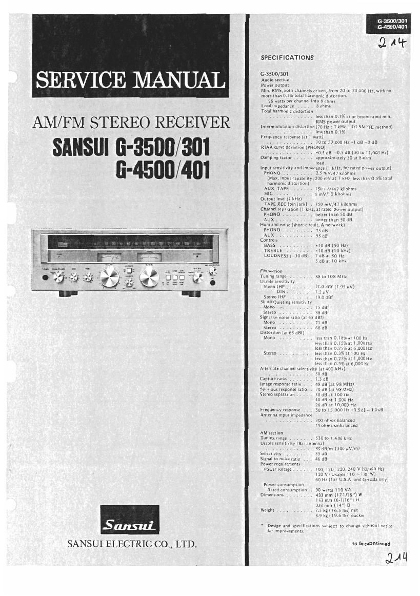
Sansui G 401 Service Manual

This is the 12 pages manual for Sansui G 401 Service Manual.
Read or download the pdf for free. If you want to contribute, please mail your pdfs to info@audioservicemanuals.com.

Page: 1 / 12
left right
Sansui G 401 Service Manual

Extracted text from Sansui G 401 Service Manual (Ocr-read)


Page 2

6-3500/301

6-4500/401

SPECIFICATIONS

(3-4500/401
Audio union
Power autpur
Mill. RMS, both channels driven, from 20 to 20,000 Hz, with no
more than 0.1%ioral harmonic distortion.
#0 watts perehannel into 3 ohms
Load impedance . , . . a ohms
Total harmonic dislortion
............. less lhifl 0.1% itor below rated rnirl.
RMS power DUKPlll
lnrerrnodulariondmorrion (70 N1: 7 kl-iz- - 4:1 SMPTE method)
. Iessrnan 01%
Frequency response (at 1 watt)
. .. .. liotosoooohzolds ads
(mono)
. +0.5 as -:l.s an (ac to 15,000 Hz)
, approximately 30 at eohm
load
lnpursensirivityana lmpedahfiefl kHz Iorraled pnwerourpux)
PHDNO . . . 2. Sme kilohms
(Max. inputeapahil y, 200 mV ail kHz, lessthan0.5%toul
harmonic dislorllarl]
Aux, TAPE ,
MIC
Output level ll kMxl
TAPE REC lvrniack) . iso mVIA'l kilohms
Channel separation (l kHz, ai rated power output)

Darnpi g akin}

. lso «iv/47 kilnhms
, 8 mVI'lO kilohrns

Hum and noise isnorrcircuil, A network)

PHONO .

Aux..... .9Sda
Controls

BASS ,,,,,,,, :IO aalso Hz)

TREBLE MG dBilOka)

Louonzssi 'aoaa) 7 dBat 50 Hz
5 as at 10 kHz


FM section
Tuning range ....... es in ice MM:
Usable semiriviiy
Mona ll-tF .. . Il,oaef(l.9suvi
DlN.1.7 uv
Stereo |Hf . 19.0 dBf
50 dB Quitting wnstlivilY
Mono 5 dB!
Stereo . 33 dB!
Signal to noise ratio (ar 55 earl
Morin . , I 13
Stereo . . GE dB
Distortion in as
Mono .......... less than 0. E at 100 Hz

less (hm 0.15% at man Hz
less than 0.25% at 6.000 Hz
Stereo .......... less than 0.3% at 100 Hz
less rhan 0.25% 111,000 Hx
less than 0.3% at 6,000 tiz

Capture ratio . . 1.3 as
Image response ratio . as an [at as Mi-ix)
Spurious response rat . to as (I! 93 MHz)
Srereu separation ..... 30 an ar inn H1

an as 1.000 Hz

25 as at rooou N1
Frequency response , , 30m is,ooo Hz onsaa -1.oae
Antenna input impedance

. . . . . , , . 300 ohms balanced

75 ohms unbalanced

AM section
Tuning range ....... sao Iol ,500 kHz
Usable sensitivity (Bar antenna)

.............. so dB/m (300 uv/ml
Seleczlvily (:10 kHz) as an

Signal to noise ratio , . . 46 dB
Power requlrcments
Power voltage ...... l0l],17£l,220 2w v {so/so H1)

l20 V(Usable no ~130V)
so Hz (for u s A and Canada only)
Power eonsumprlon
Rated consumption . 115 watts Ms VA

Dimensions ..... . 4:3 mm li7-lllé"]w
153 mm (oi/ls") H
354 mm m) D

Weight ........... u min res) ner
9.5 kt 120.9 lbs) paekea

rHoNo . , better than 50 dB

AUX bmenhm 50 dB Alternate channel selectivity (ar 400 kHz) Design and specifications subieer ro change without notice

.............. sods ' forlmprovemenu.

1. OPERATIONS

Pop-noise preventive circuit

In order to prevent the annoying pophoise to the loudspeakers at
turning the power of the amplifier ON, the pop-noise preventive cir-
cuit adopted in the 6-4500/401 is the combination of the conven-
tional driver-voltage delay type used in the power supply (rectifier)
circuit and the NF delay type pop-noise preventive circuits. The
configuration of NF delay type pop-noise preventive circuit is
shown in Fig. l.

in this circuit, the switching (ON-OFF) of the transistor TR05 is
made by the time constant of the capacitor C40 and resistor R88.
Thereby the NF resistor, R51 is controlled, and the gain of the main
amplifier stage is lowered when TROS is ON, thus the voltage drift
(transient voltage) of the main amplifier at turning the power ON fig. 2
does not appear on the speaker terminals for very short period of
time. In other words, at the instant that the power is turned ON,
the voltage at the point A rises up to +13V, then the voltage de»
creases by means of the time constant of C40 and R88 as shown in
Fig. 2. At this time, the diode D11 is inversely biased, consequently,
the potential voltage of the point B is 0V as Fig. 3. Because of thls,
TROS turns to the cutoff, thus the NF resistor, R51 acquires such a
state as its resistance value becomes equivalently very large, which
deCreases the gain of the power amplifier. When the charge of the
C40 is completed, the voltage of the point B (see Fig. 3) becomes
negative, as a result, the diode DH is biased. Therefore, TROS is
turned 0N and the circuit of this equipment is normally operated
approximately 2 seconds after the power is turned ON to prevent
the pop noise which flows to loudspeakers.

+13V

e -2V

Time-> i

VOLTAGE»
o

'r->From this point the set begins
9 2 seconds ->i working normally

Power 0N
Voltage variation during a certain period
of time at ®

VOLTAGE+
o

Fig. 1 Fig. 3 Voltage variation at
Rs: _
Amw- to speaker terminals
IC01
021
R51

Page 9

G-3500I301 1 6-3500/301

6-4500/401 7 5-4500/401

6. OTHER PARTS

6-1, Front View 6-2. Top View
6-3500/4500/401 Only

TR 16 TR17 TR15

l F-2924 A
x , /. _ . / .1 '32)
15»; 2 1:37 112/ (13+) 11;» m» V
/F\
.- 31/1
Parb L13: 1From & Top View)
Pars No. Stock No Description Pam No. Stock No. Description
1 15727160 Wood Bonnet 15408662 D161 Scale 16735001
15236690 W B. Type Bushing 15/408502 DlalSCalE1G-301) n;
7007631 Front Panel Assv 16-3500/45001 19 {5408572 Dual Scae1Gr4SOO) H
2 L7008001 Front Panel Ass'y 16-3011 5408512 Dlal Scare 167401) B
'7008011 Front Pane1 Assv 1674011 5305720 Backside Panel for r1151 scale F t}!
3 5306690 lnslde Panel 20 7115032 Dial Pomter Assy 5-2-71? LI-
4 5426410 Power lllumlnalor Bar 21 43011201 Tunlng Meter L ..... J
12430320 HESODhCIlE JECK Socks! 2 430111111 Signal Merer
5 i 16-350014500/4011 23 2450070 AC Ouzlet
2430340 Headphone Jacx Socket 10-3011 24 3910600 Stram Relre Dower cord
15319142 Power & Sneakers Swncn Knob 25 38004701 AC Cord
11190530 Pawer Ratary Swncn 16 2011 26 2210340 4P Speaker Termlnal
6 11101850 Power 8, Speaker Florarv Swncn 2 22004101 8P Input Terminal
; 16-3500/4500/401) 29 2230180 Ground Termlnal
5235470 Mg )1 7 , spacer I101 30 2210330 41" Antenna Terminal
7 15313133 BASS Volume Knob 1 6146670 3744 Tyoe Pulley
110153001 100141 x 2 Bass Volume 32 4200760 Bar Antenna
8 ( 5219133 Treble Volume Knob 33 5289171 Ear Anrenna Holder
1101 53001 1ODKSZ x 2 Treble VDlvme 34 7036590 Tunlng Unit
9 15318981 Volume Knob 35 7136101 Tenslon Unlt
110111301 250k0181x 2 Valume 36 0400650 Pilot LampAss'y
10 15319133 Balance Volume Knob 4002880 Power Transformer 1673500)
1005350, 1 25mm 181 Balance Volume 37 14002884 Power Transformer 16-301)
11 15328690 Loudness Swncn Knob 14002870 Power Trans1ormer 1045001
111314901 Loudness Swnch Y4002874 Power Transrormer15 4011
1;; 5318972 Tuzvlng Knob
55326690 Knob tape monltur switch TR15, 16 0306541,2 28C198610,Y1} T .
13 111310601 TdOE Monitanw'ltcl-l 15117.18 030091112 ZSA771 (Q'y) ransustor
15319142 Selector Switch Knnb 5288721 Flaw 1m TR
14 11101840 SelectorSwitch 10659801 OO1uF 150V CC. xx, UL
15236470 N19 X 7 sDaCEr nut C 701 10598107 0.011.413 250V MC. EU, BS
(15058791 Rmmm Plate 0659811 0 OMF 125V C.C. CS
5 :6517250 Leg n
1 2430370 Microphone Jack Socket
17 {5319133 Mlcrophone Mixlng Volume Knob
10053401 ZOKFL 1A) Mic Mixing Volume
[0319060 LE Du FM Stereo ind'caror
18 15289180 L E D Holder
l5136030 Plastic Rivet