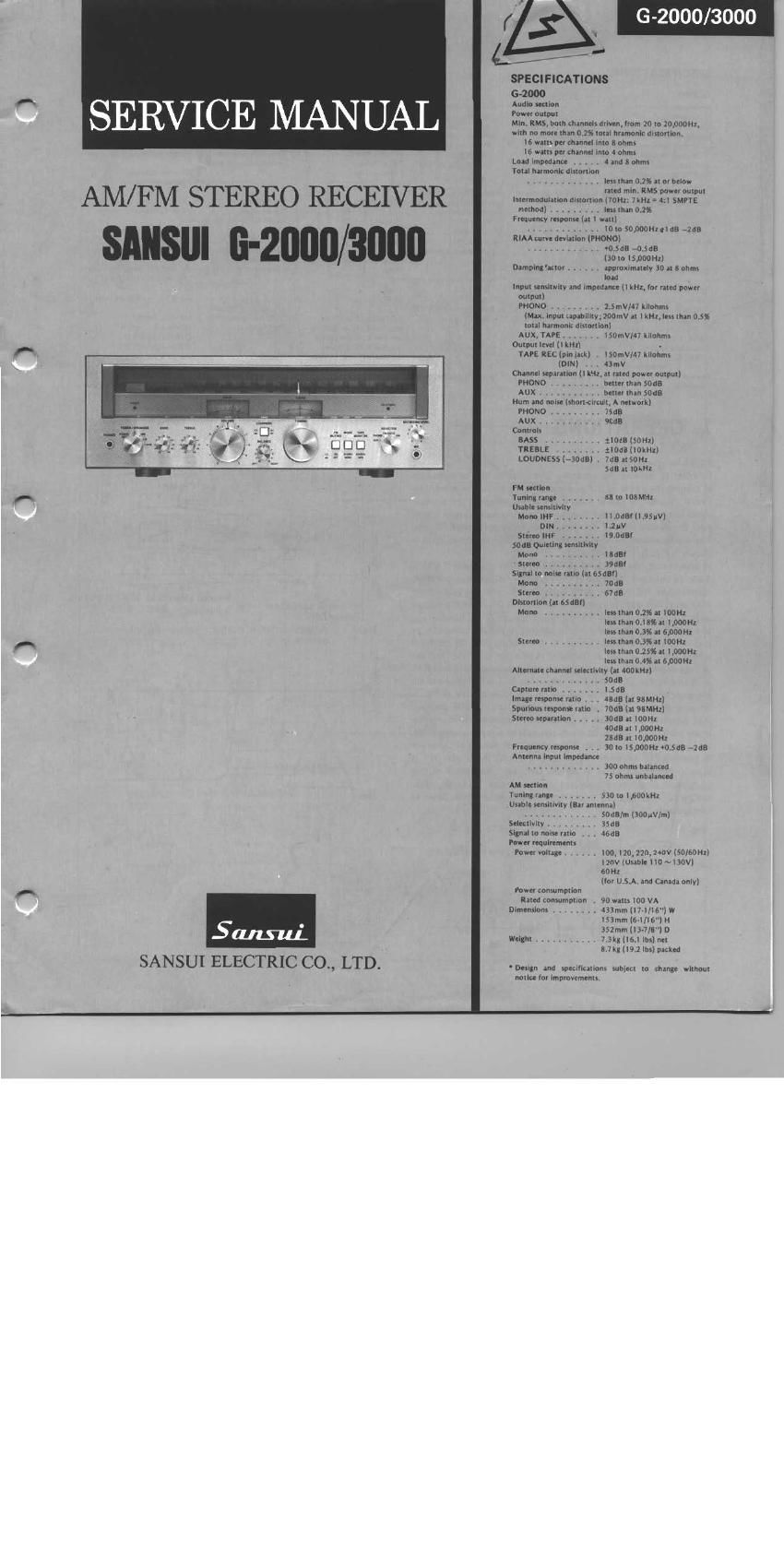
Sansui G 2000 G 3000 Service Manual

This is the 18 pages manual for Sansui G 2000 G 3000 Service Manual.
Read or download the pdf for free. If you want to contribute, please mail your pdfs to info@audioservicemanuals.com.

Page: 1 / 18
left right
Sansui G 2000 G 3000 Service Manual

Extracted text from Sansui G 2000 G 3000 Service Manual (Ocr-read)


Page 1

G-2000/3000

SERVICE MANUAL

Page 2

G-2000/ 3000

SPECIFICATIONS
6-3000

Audio section
Power output
Min, RMS. both channels driven, lrom 10m 20.000Hz.
with no more than 0.I 5% total hramonlt distortion.
26 watts per channel into 8 ohms
2n watts per channel into 4 ohms
Load Impedance . 4 and 8 ohms
Tolal harmonic distortion
less than 0.15% at or below
med min. RMS power oulDur
inlermodulatlon aismmon (70m. 7kHz : Azi SMPTE
memod) ..... . lessman 015%
Frequenty response [at 1 wall)

Hum and noise (short-circuit, A network]

PHONO V . 75m:
Aux . soda

Controls

BASS . ,, . . :lOdEISOHz)
TREBLE . tiDdBllOkHzl

LOUDNESS (*30d3l . "It? at SOHI
sets at iOkHz

FM section

Tuning range ......

Usable sensitivity
Mono lHF

88m 108MHz

. ll.0dBfll.95uVl

Image response rarlo . . . 48:15 (at 95mm \

Spurious response ratlo . 70:18 (at 98MH1I

Stereo separation ..... soul; in iOOHz

40:13 at moon:

2305 at 10,000 Hz

Frequency response . . . 30(015,000H1 v0.5dB qua

Antenna mpul Impedance

............. 300 ohms balanced

75 ohms unbalanced

AM section
Tuning range ....... 530to1,600kH2
Usable sensitivity lEar antenna]

............ IOKO 50.000Hz +IdB 72:18 DIN . IVZMV .. . V , V V. . .. SDdE/m lSODuV/ml
RIAA Curve deviation (PHONOi Stereo IHF . IQVOdBf Selectivity . V . . , 35dB
V +0.5ae 70.5w SOdBQuIeting scnsltlvlty Signal to nolsc no . . . aeua
(30 IO iS,DDl>HZ] Mono . , . V V . léldflf Power requirements
Damping mm: ..... approximately 30 318 ohms 5mm . V . . . 39am Power voltage ...... iOO. I20. 220, 240v (salsoni
load Slgnal m n0lse ratio lat SSdBfi i20V (Usable I IO ~130V]
input senslilvlly and Impedance (1 kHz, for rated power Mono 70GB fiDHz
output) Stereo . 67dB [for US A. and Canada only)
PHONO ,,,,,,, V 2.5 mV/47 kllohms Distortion lat ESdBf] Power consumption
(Max. Input Lapabllllv, 200mV al IkHZ, Iessxhan 0.5% Moria ....... . less than 0.2% at IODHZ Rated consumption IQD watts I40 VA
|utal harmonic distortion) less than Oil 3% al l,000H1 Dimensmns . V 433mm 7.1 /l 6"} W
AUX,TAPE V . lSDmV/47 kiiohms lessrhan0.3%ar6,OOUI-I1 ISSmm [érllitfliH
cumin lcvel (lktizl smee . . . less than 0.3% u loom 352mm Ilsa/w D
TAPE REC (pin lack) . l50mV/47 kllollms Itssthan 025% at l,000HZ Weight . 8kg 7.6 lbs) net A

less than 0.4% at 6,000H1 9.4 kg (20,7 lbs) packed
Alternate channel selectivily (at worm)
SOdB *Deslgn and specifications same u change wnnnm

Caprurelatlo, . .. i.SdB nonceforimpmvemenis,

lDlNi V ,. 43mV
Channel senarallon ( i kHz. at rated power output)
PHONO ........ belterlnan SOdB
AUX . V belterlhnn 5063

1. OPERATIONS

Pop-noise preventive circuit

In order to prevent the annoying pop-noise to the loudspeakers
at turning the power of the amplifier ON, the pop-noise preventive
circuit adopted in the 6-3000 is the combination of the conven-
tional driver-voltage delay type used in the power supply (recti-
fier) circuit and the NF delay type pop-noise preventive circuits.
The configuration of NF delay type pop-noise preventive circuit is
shown in Fig.1.

In this circuit, the switching (ON-OFF) of the transistor TROS is
made by the time constant of the capacitor C40 and resistor R88.
Thereby the NF resistor, RSI is controlled, and the gain of the
main amplifier stage is lowered when TROS is ON, thus the voltage
drift (transient voltage) of the main amplifier at turning the
power 0N does not appear on the speaker terminals for very short
period of time. In other words, at the instant that the power is
turned ON, the voltage at the point A rises up to +13V,then the
voltage decreases by means of the time constant of C40 and R88
as shown in Fig. 2. At this time, the diode D11 is inversely biased,
consequently, the potential voltage of the point B is 0V as Fig. 3.
Because of this, TR05 turns to the cut-off, thus the NF resistor,
R5] acquires such a state as its resistance value becomes equiva-
lently very large, which decreases the gain of the power amplifier.
When the charge of the C40 is completed, the voltage of the point
B (see Fig. 3) becomes negative, as a result, the diode DH is
biased. Therefore, TRos is turned 0N, and the circuit of this
equipment is normally operated approximately 2 seconds after
the power is turned ON to prevent the pop-noise which flows to
loudspeakers.

Fig.1

+1§v

e-ZV

O

Time-> 1 4
2 2 seconds 'g->From this point. the set begins
Power ON E. worklng normally.

ig. 2 Voltage variation during a certain period
of time at ®

-n VOLTAGE-é

O

Time->

VOLTAGE~>

~O.72V%

.
(-2 seconds-a;
.

Fig. 3 Voltage variation at CB)

.1 ,RVEAL7-to speaker terminafs

Em

(321

TR05