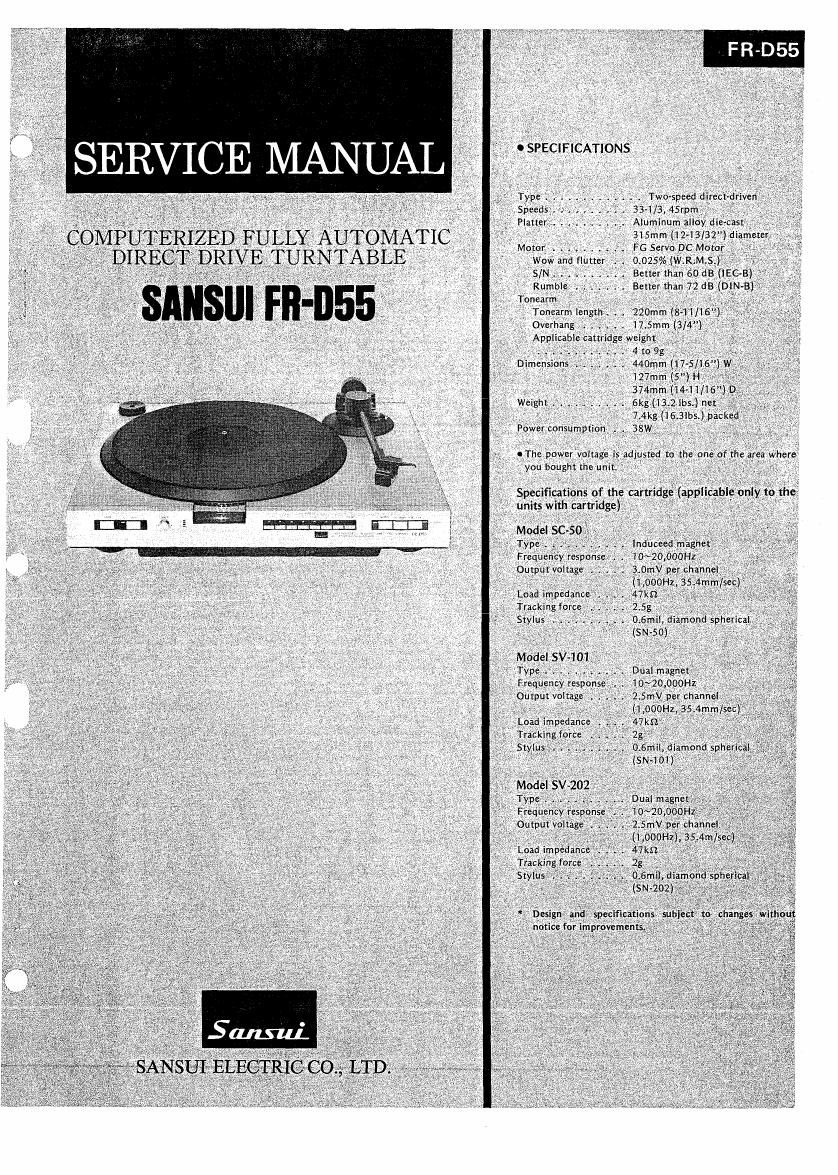
Sansui FR D55 Service Manual

This is the 17 pages manual for Sansui FR D55 Service Manual.
Read or download the pdf for free. If you want to contribute, please mail your pdfs to info@audioservicemanuals.com.

Page: 1 / 17
left right
Sansui FR D55 Service Manual

Extracted text from Sansui FR D55 Service Manual (Ocr-read)


Page 2

1. OPERATION

The FR-DSS is a computerized full automatic music selection turn-
table in which a mechanism that can automatically select any music
on a record disc at random.

Refer to XR-Qli SERVICE MANUAL, for basic operations which
are almost equal to this model.

The control circuits for FR-DSS can mainly be divided into a servo
circuit to control a DD motor and a microcomputer and its peri-
pheral circuit to mainly control a tonearm.

Refer to FR-D45 SERVICE MANUAL, for operation of the servo
circuit, since the operation is entirely the same as in the FR-D45.

1-1. Basic circuit configuration for full automatic
operation (See Block Diagram on Page 2.)

A. Microcomputer

The microcomputer uPDS46C-181 controls the operations of the
tone arm, lifter, and DD motor in such a way that every control sig~
nal is output to the corresponding output port after each of signals
applied to the input ports has been executed in accordance with a
program stored in the microcomputer memory.

The microcomputer becomes enable only when the output ports are
at H level in potential; in other words, every circuit connected to
pins (at H level) of the microcomputer operates.

B. Input peripheral circuits for the microcomputer

1. Control switches

These are manual operation switches to perform the full automatic
operation. Since the control switches are dynamic-connected to the
ports of the microcomputer, if a control switch is pushed, two
Input/output pins are connected to each other in the microcomputer
and thereby the microcomputer begins to operate. (See Block Dia-
gram.)

2. A sensor and the sensor circuit

In operation with the B sensor, the A sensor detects the tonearm
positions necessary for automatic operation. In other words, the A
sensor detects the lead-in position of a 30cm- or I7cm~size record
disc and also detects whether the tonearm rests on the arm rest (A
x B=I)ornot(AxBa¢ 1).

The tonearm positions (A x B = I and A x B 55 1) have the following
relations to the start/step switch:

0 If START/STOP switch is set to start (The turntable is
at a stop)

. . Lifter Operation of Aummatie
Am 5" Position Turntable Operation
0n the rest Up [D = 1) Rotates after In-operation
(A X 3 = 1) ZOOms
Same as above Down (C ,= I) ln-operation after
D = 1 in CW
0" the record disc Up (D E 1) Immediately To C = I in CW

IA x B a! 1) rotates

Same as above Down (C = 1)

o If START/STOP switch is set to stop (The turntable is in
motion and also in automatic operation.)

. . Lifter our on of Automatic

Am "mm Position Turntable Operation
On the rest Up (D = 1) Immediately
(A x B = 1) rotates
Same as above Down (C x I)
On the record disc Up (D = 1) Stops at point Arm return
(A X E ii 1) AB
Same as above Down (C = 1) Arm return

0 If START/STOP switch is set to stop (The turntable is in
motion and also in automatic operation.)

. . . Operation of
Ann Motion Status Automatic Operation Turntable
During up motion Out of automatic operation Immediately stops
(AxB=1) atD=l)
During up motion Arm return after D a I Immediame stops
(AxB# 1) atpointAE
During horizontal Immediately out of automatic Immediately stop:

motion (A x B =1) operaimn »

During horizontal Arm return in CCW ->CW

Stops at point
motion (AXE? I) or in CCW AE

During down Arm return after D = 1 Same as above
motion (A x B #1)

During return Disable

motion

Note: In the above lists, A x B =1, D =1, and C =1 mean the states
in which the sensors B,C, and D are detecting the correspond-
ing signals, respectively, on the timing chart. CW means that
the micromotor rotates clockwise; CCW means that the
micromotor rotates counterclockwise. Refer to the respective
sections for operations of the sensors A, B, C, D and the
mlcromotor.

The signal detected by A sensor is applied to the input terminal 33

of the microcomputer through flcmb and flcm c.

3. B sensor and the sensor circuit

In cooperation with the A sensor, the B sensor detects the tonearm
position and the end detection signal in the record lead-out groove
after finishing over play.

The signal detected by the 8 sensor is applied to the input terminal
34 of the microcomputer through transistor 2;, and med.

4. C sensor, D sensor and the sensor circuits

The C and D sensors comprise a lifter cam and the micro-switches,
respectively. The C sensor detects the down-position of the lifter;
the D sensor detects the up-position of the lifter.

In the both sensors, the terminal 2 of each micro-switch is shorted
to the ground whenever the lifter states are detected.

5. E sensor and F sensor

The E and F sensors mounted within the head shell feed into the
microcomputer the signals necessary for automatic disc slze selec-
tion and automatic music selection. In other words, in order to
implement complex full automatic operations, both the sensor sig-
nals are fed into the computer after being discriminated into E2, E3,
F1, and F2, respectively, through appropriate circuits.

The arrangement of the E and F sensors is shown in Fig. H, and E
sensor ls called a leading sensor because E sensor first detects the
signal.

n