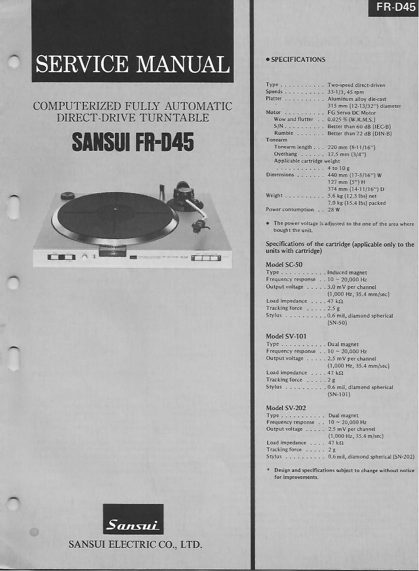
Sansui FR D45 Service Manual

This is the 16 pages manual for Sansui FR D45 Service Manual.
Read or download the pdf for free. If you want to contribute, please mail your pdfs to info@audioservicemanuals.com.

Page: 1 / 16
left right
Sansui FR D45 Service Manual

Extracted text from Sansui FR D45 Service Manual (Ocr-read)


Page 1

SERVICE MANUAL

Type ........... Two-speed direct-driven
Speeds . . 33-1/3,45 rpm
Platter .......... Aluminum alloy die-cast

COMPUTERIZED FULLY AUTOMATIC MW ........ inc
DIRECT-DRIVE TURNTABLE Wowandflutter I: 0.025%(W.R.M.S.)

S/Nl . . l . . . . Better than60 dB (lEC-B)

Rumble ....... Better than 72 dB (DlN-B)
- Tonearm
Tonearrn length. . . 220 mm (S-ll/lfi")

Overhang ...... 17.5 mm (3/4)
Applicable cartridge weight
...... 4t010g
Dimensions ....... 440 mm (17-5/16) W

127 mm (5) H
374 mm (14-11(16) D

Weight .......... 5.6 kg (123 lbs) net
7.0 kg (15.4 lbs) packed
Power consumption . . 28W

I The power voltage is adjusted to the one of the area where
bought the unit.

Specifications of the cartridge (applicable only to the
units with cartridge)

Model SC-50

Type ........... Induced magnet
Frequency response l . 10 ~ 20,000 Hz
Output voltage ..... 3.0 mV per channel

(l,000 Hz, 35.4 mm/sec)
Load impedance . . . .47 kn

Tracking force ..... 2.5 g

Stylus .......... 0.6 mil, diamond spherical
(SN-50)

Model SV-101

Type ........... Dual magnet

Frequency response . . 10 ~ 20,000 Hz

Output voltage ..... 2.5 mV per channel
(1,000 Hz, 35.4 mm/sec)

Load impedance . . . .47 km

Tracking force ..... 2 g

Stylus .......... 0.6 mil, diamond spherical
(SN-101)

Model SV-202

Type . .......... Dual magnet

Frequency response l . 10 ~ 20,000 Hz

Output voltage ..... 25 mV per channel
(1,000 Hz, 35.4 m/sec)

Load impedance . . . , 47 km

Tracking force ..... 2 g

Stylus . . l . . ..... 0.6 mil, diamond spherical (SN-202)

* Design and specifications subject to change without notice
for improvements.

SalLs-uj.
SANSUI ELECTRIC C0,, LTD.

Page 2

1. BLOCK DIAGRAM

c SENSOR 23
D SENSOR ' 2
SPEED SELECTOR W 5

I- my

.5v 5

r1c2
START/STOP k» 4
LIFTER 5
REPEAT 3
MICRO
Wavengm shelling arm/r COMPUTER
Time 2
C
A SENSOR , l 1 PD 55:
. . ~045
B SENSOR l0L,fICid i 22
.

25

Dr/Ver
15-» rats @ REPET :x:
Dr/Ver w
19 r017 i» {j COMPUTER 15.:

MlEro Motor Coma! CIrCLHl
#777" *_-""T '7"?
l .
'0 l ram, 111 l MICRO
l _¢_ .>
1i -+-->fICla f012, f013 l MOTOR
. T
1____L,,,, S____l
Plunger DIIVE Clrculi
127 foil. r015 % PLUNGER
' SOLENOID

v f018

Disk SIZE Detector CerU/I

2. OPERATIONS

2-1. General

This model, FR-D45 is provided an automatic disk size detecting
function in addition to the full automatic system of Sansui FR-D4/
QS.

* See FRvD4 Service Manual for operations of the antomatic
mechanism assembly, arm position sensor, and lifter position
sensor.

* The control circuit of the FR-D45 is divided into three portions:
a servo circuit to control the DD motor, a microcomputer
pPD554C to control the tone arm mainly, and its peripheral cir-
cuits.

See XR-QQ Service Manual for operations of the microcomputer
uPD554C and its pheripheral circuits.

* The automatic disk size (30 cm and 17 cm] detection is carried
out by placing a prism between the LED (fLDi) in Fig. 2-1 and
the photo-transistor f0] 9. In case of a 30 cm disk, the light from
the LED is intercepted by the disk and therefore the photo-tran-
sistor fQi9 is turned OFF. In 17 cm disk, the lightfrom me LED
reaches the photo-transistor fQi9 through the prism and there~
fore the photo-transistor fQiQ is turned 0N.

L ,l,

185D. 285D
MOTCR CSNTRC;

3 RC

The ON/OFF signal detected by the photo-transistor is then in-
putted to the pin No. 6 of the microcomputer uPDSS4C. The
potential level of the pin No. 6 is in L level when the fQi9 is
OFF (30cm disk] and in H level when the fQi9 is ON (17 cm
disk).

in addition, the photo-transistor fQZO detects whether or not a
disk is placed on the turntable. When no disk is on the turntable,
the lightfrom the LED turns the fQZU ON to change the pin No.
25 of the uPD554C from L to H level. When the pin No. 25 is in
H level, the return operation is performed even by depressing the
start button.

Fig. 2-1

LED
(L01

Turntable 5*

80062