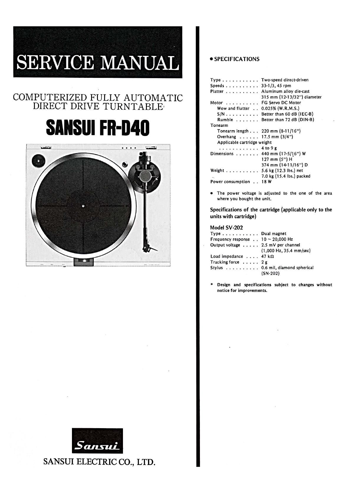
Sansui FR D40 Service Manual

This is the 16 pages manual for Sansui FR D40 Service Manual.
Read or download the pdf for free. If you want to contribute, please mail your pdfs to info@audioservicemanuals.com.

Page: 1 / 16
left right
Sansui FR D40 Service Manual

Extracted text from Sansui FR D40 Service Manual (Ocr-read)


Page 1

SERVICE MANUAL

COMPUTERIZED FULLY AUTOMATIC
DIRECT DRIVE TURNTABLE

SAHSIII Ill-D40

l 3.2; _, Q... in .

Smut-la:
SANSUI ELECTRIC C0,, LTD.

o SPECIFICATIONS
Type ........... Two-speed direct-driven
Speeds .......... 33-1/3, 45 rpm
Platter .......... Aluminum alloy die-cast
315 mm (12-13/32") diameter
Motor .......... FG Servo DC Motor
Wow and flutter . . 0.025% (W.R.M.S.)
S/N .......... Better than 60 dB (lEC-B)
Rumble ....... Better than 72 dB (DIN-B)
Tonearm
Tonearm length . . . 220 mm (8-11/16")
Overhang ...... 17.5 mm (3/4")
Applicable cartridge weight
............ 4 to 9 g
Dimensions ....... 440 mm (17-5/16") W
127 mm (5") H
374 mm (14-11/16") D
Weight .......... 5.6 kg (12.3 lbs.) net
, 7.0 kg (15.4 lbs.) packed
Power consumption . . 18W

0 The power voltage is adjusted to the one of the area
where you bought the unit.

Specifications of the cartridge (applicable only to the
units with cartridge)

Model SV-202

Type ........... Dual magnet

Frequency response . . 10 ~ 20,000 Hz

Output voltage ..... 2.5 mV per channel
(1,000 Hz, 35.4 mm/sec)

Load impedance . . . . 47 kn.

Tracking force ..... 2 g

Stylus .......... 0.6 mil, diamond spherical
(SN-202)

Design and specifications subject to changes without
notice for improvements.

Page 2

1. BLOCK DIAGRAM

SWI _ flC2a
START/STOP 54% 9 '11 K3 JUL m -COMPUTER
UP/DOWN 3&8 932 R2 0 4 9LDz
3 _
REPEAT ---o'2' 9 K' oI
, MICRO QLD'
I7cm oIsc COMPUTER REPEAT
fLD4
Sensor17 f09 fie
,LKW-W
I. _
Sensor 30 \ E: fOIo 9'0 C21
. ll fOIZ 'lmnm' Ra 1-1-7W DD MOTOR
"\30cm Disc CONTROL
flCI (285D)
M88844-543M
fLDI fIC2u
2. K Io. DD-2 52
J-L
-02 fIC2b
2- K f02 MDcIs 53
fLDa
flC2c
7. K ma 9 I0 a, _m_
06 NC:
_LnJ'll|l
Screen P'O'e 07 --IL MICRO MOTOR DRIVE
LIFTER CAM n I
\_----.
_SensérD I
_l_|_ @ TONE ARM
MICRO MOTOR

LIFTER

2. OPERATIONS

2-1 . Outline

The FR-D40 is a fully~automatic disc-selectable system turntable in
which a newly-developed automatic mechanical assembly is con-
trolled by a microcomputer.

The control circuit of this turntable includes an operation switch
section, a tone-arm position detection circuit made up of a slit plate
and three pairs of light emitting diodes (LEDs) and phototransistor,
an arm lifter position detection circuit made up of a lifter cam and
two microswitches, a micromotor drive circuit, and a microcom-
puter M88844-543M.

Additionally, an automatic disc selection function is provided which
is realized on the FR-D45.

2-2. Automatic Mechanical Assembly Operation

Tone arm lead-in and lead-out operations and arm-lifter up/down-
operations are performed when the micromotor rotates clockwise
(CW) or counterclockwise (CCW).

The tone-arm position is detected by combination of the LEDs, the
phototransistors and the slit plate; the arm lifter position is detected
by the two microswitches and the lifter cam; the micromotor ro-
tation direction is determined by the operation switches.

1) Torque transmission route in lifter drive

When the micromotor rotates in the CW or CCW direction, the
torque is transmitted from the motor, through a belt, a worm gear, a
drive gear, two floating gears (l and II), a cam gear, a lifter cam, to a
lifter guide, so that the arm lifter moves up or down. (See Fig. 2-1)

2) Torque transmission route in tone-arm drive

When the micromotor rotates in the CW or CCW direction, the
torque is transmitted from the motor, through a belt, worm gear, a
drive gear, two floating gears (I and 11), two drive pulleys (I and 11),
to a TA drum, so that the tone-arm moves in the lead-in or lead-out
direction.

3) Switching between lifter operation and tone-arm opera-
tion by cam gear

The lifter operation and the tone-arm operation are switched by

using two cutout portions (1 and 11) formed in the cam gear. (See

Fig. 2-4)

When the floating gears rotate and therefore the contact point of

the floating gear with the cam gear reaches the cutout portion of the

cam gear, the floating gear drops into the cutout, so that no torque

of the floating gear is transmitted to the cam gear.

On the other hand, while the floating gear is in the cutout portion

of the cam gear, the drive pulley concentrically fixed to the floating

gear shaft is brought into pressure-contact with the TA drum.

As a result, the revolution force of the drive pulley rotates the TA

drum, so that the tone-arm is moved.