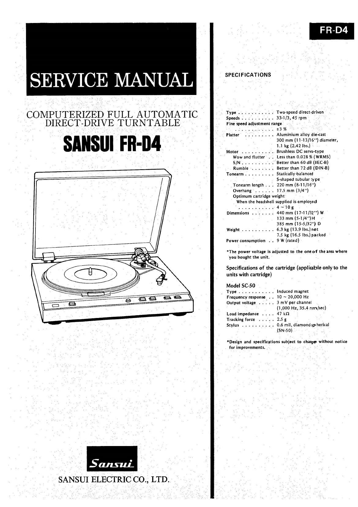
Sansui FR D4 Service Manual

This is the 11 pages manual for Sansui FR D4 Service Manual.
Read or download the pdf for free. If you want to contribute, please mail your pdfs to info@audioservicemanuals.com.

Page: 1 / 11
left right
Sansui FR D4 Service Manual

Extracted text from Sansui FR D4 Service Manual (Ocr-read)


Page 1

SERVICE MANUAL

COMPUTERIZED FULL AUTOMATIC

DIRECT-DRIVE [TURNTABLE

snusur rn-n4

\

SANSUI ELECTRIC CO., LTD.

FR-D4

SPECIFICATIONS

Type ........... Two~speed direct-driven

Speeds .......... 33-1/3, 45 rpm

Fine speed adjustment range

...... . . . . . . :3 %
Platter . . . . . Q . . . Aluminium alloy die-cast
300 mm (I 1-13/16") diameter,
1.1 kg (2.42 lbs.)

Motor .......... Brushless DC servo-type
Wow and flutter . . Less than 0.028 % (WRMS)
S/N .......... " Better than 60 d8 (lEC-B)
Rumble ....... Better than 72 dB (DIN-B)

Tonearm ......... Statlcally-balanced

S-shaped tubular type
Tonearm length . . . 220 mm (8-11/16")
Overhang ...... 17.5 mm (3/4")

Optimum cartridge weight
When the headshell supplied is employed
........... 4 ~10 g
Dimensions . . ..... 440 mm (17-11/32) W
133 mm (5-1/4")H
385 mm (15-5/32) D

Weight .......... 6.3 kg (13.9 lbs.) net
7.5 kg (16.5 lbs.)packed
Power consumption . . 9 W (rated)

*The power voltage is adjusted to the one of the area where
you bought the unit.

Specifications of the cartridge (applicable only to the
units with cartridge)

Model SC-SO
Type ........... Induced magnet
Frequency response . . 10 ~ 20,000 Hz
Output voltage . . Q . . 3 mV per channel
(1,000 Hz, 35.4 rum/sec)
Load impedance . . . . 47 km
Tracking force ..... 2.5 g
Stylus .......... 0.6 mil, diamondsp herical
(SN-50)

*Design and specificetions subject to change without notice
for improvements. 1

Page 2

FR-D4

1. BLOCK DIAGRAM

» CONTROL SECTION
-. I - _ . ' I
__s 0030_ _[ . 33/45
' ICOI I
cum fl . 184D _: DDMOTOR
START/STOP SWOl} DD- KO MlCROr I I ICOQe START/STOP ' CONTROL CIRCJI)
: COMPUTER ,
REPEAT SW02 K1 03 fl ' REPEAT
TR03 - Q10
SPEED 33/45 SW03 ,_.I I-> K2 E LED702
SELECTOR 1 Icon
RECORD SIZE K3 R8 ************ -
SELECTOR 30/ 17 SW04 4 I003c.d _ M38844 _Li_ TR02
, >1) ' R7 R0 cw ASTABLEMULTIVIBRATOR I
________ __ _,__M.. i: i: R6 W ICOAa. s. ICOZd Al; LED701
|CO3e,f Rx
R4 Lr
R5
I __ I
' Rm R2 MICROMOTOR CONTROL CIRCUlT
. IT
WAVE SHAPING CIRCU [CW d, Tm; H
_ ICOdc d j )0 I
l I ICOZl 39.1ng
I I
TRlB WIN-If: m0),
CW/CCW
MICROMOTOR
DRIVING MECHANISM
M : V . for TONEARM and ARM LIFTER
; CW/CCW ,,,,,
» F
.1OWBM-POET9N EEN-SOBI 9W PLUNGER=CLUTCH
' I EWII'21i'SE1IUfII I
l 9 5" WW I c V PLUNGER ONI PLUNGER OFF
I A» ARM LIFTER
I Tonearm Descending I I I l
I positionIBO/Nlmtectun l l 1 I
E a J
I_ _______ _| I - BRAKE SHOE J I I
_______ a I
I '- l I I
I CFSENSOR I . I
| Lowest Pusmon l ' I CW -- - CLOCKWISE
I 3 I ccw I- COUNTERCLOCKWISE
I D'SENSOR I
I ItIghes: Fasten I
L _________ J
ARM LIFTER POSITION SENSOR

2. OPERATION

2-1. Construction of Full-Auto System
(See Block Diagram)

The full-auto system adopted in this model is composed of 1) Driv~
ing mechanism Assy for tonearm and arm lifter (here after called
driving mechanism assy), 2) Electrical control section governing the
driving mechanism assy.

Arm position sensor (A-sensor, B-sensor) and lifter position sensor
(C-sensor, D-sensor) are attached to the driving mechanism assy and
detecting vertical and horizontal position of tonearm. The control
section composed of one Chip micro computer (M38844) and peri-
pheral circuits controls 1) rotation of DD Motor 2) lead-in, return
and repeat of tonearm function 3) up or down of lifter operation
corresponding to the states of arm position sensor, lifter position
sensor and operating switch.

2-2. Movement of driving mechanism assy and
function of arm position sensor, lifter posi-
tion sensor.

1. Movement of driving mechanism assy (See Fig. 2-1 , 2-2)
The configuration and side view of driving mechanism assy and gear
train from micro motor are indicated in Figs. 2-1, 2-2.

The torque of micro motor to drive tonearm and arm lifter is pro
pagated from worm gear Assy =>gear (1) =>gear (3) =>friction pul-
ley => friction disc => plunger => clutch plate that clutch plate starts
rotation. Since clutch plate and friction disc are fixed to plunger,
rotation of friction disc is directly transmitted to clutch plate.
Clutch plate is depressed to the gear (2) while plunger solenoid
being OFF, however, when it becomes ON, the clutch plate is re-
leased from gear (2) then depressed to TA drum. Therefore while
plunger solenoid being ON tonearm is driven, and it being OFF arm
lifter and brake shoe are operated to transmit the micro motor tor-
que from clutch plate =7gear (2) =>lifter cam.

As brake shoe is depressed to TA drum while arm lifter being arised,
tonearm is restricted not to move excessively by its inertia during re-
turn and lead-in operation. When the lifter is completely lowered,
brake shoe is released from TA drum that tonearm is free from the
brake,