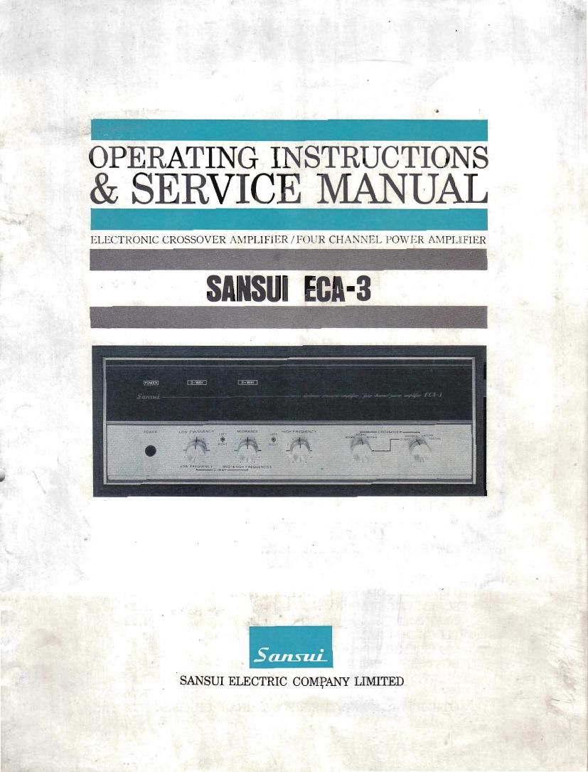
Sansui ECA 3 Service Manual

This is the 41 pages manual for Sansui ECA 3 Service Manual.
Read or download the pdf for free. If you want to contribute, please mail your pdfs to info@audioservicemanuals.com.

Page: 1 / 41
left right
Sansui ECA 3 Service Manual

Extracted text from Sansui ECA 3 Service Manual (Ocr-read)


Page 1

OPERATING INSTRUCTIONS
& SERVICE MANUAL

ELECTRONIC CROSSOVER AMPLIFIER/FOUR CHANNEL POWER AMPLIFIER

SANSIJI EBA-3

, ISANSUI ELECTRIC COMPANY LIMITED

Page 2

Congratulations on joining the thousands of proud, satisfied
owners of quality stereo components from Sansui.

The ECA-S integrated three-way electronic crossover and four-
channel stereo amplifier is designed for use with a stereo pair of
speaker systems to accomplish the two- or three- way electronic
crossover system which has been widely acknowledged as the
most effective method of reproducing original sounds and for use
with two stereo pairs of speaker systems to achieve the exciting
four-channel stereo arrangement without need of any other power
amplifier. Crossover between low and mid ranges can be switch-
selected to 400, 600 or 900Hz. Crossover between mid and high
ranges can be selected to 4000, 5500 or 7500Hz. Cutoff can be
also switch-selected to 12 or 6 dB/octave slope at both low and
high crossovers.

This manual has been prepared to help you keep the RCA-3 'in
perfect operating conditions. It explains all of the ECA-SS
unique features, connecting and operating procedures as well as
some basic maintenance requirements.

Please read the contents of this manual carefully before operating
the ECA-3. You will then be better prepared to enjoy the en-
tirely new stereo sound to the fullest.

CONTENTS

SWITCHES AND CONTROLS ................................ 3, 4
OPERATIONS .................................................... 5, 6
iELECTRONIC CROSSOVER SYSTEM
TWO-WAY ELECTRONIC CROSSOVER SYSTEM

OPERATIONS .................................................... 7, s
PAPTHREE-WAY ELECTRONIC CROSSOVER SYSTEM
OPERATIONS .................................................... 9, 10
7FOUR-CHANNEL STEREO
HINTS ON USE ........................................ 11,12,13,14
SPECIFICATIONS/CHARACTERISTICS/ACCESSORIES
.......... 15, 16
TROUBLESHOOTING CHART .............................. 17, 18
SCHEMATIC DIAGRAM ...................................... 19, 20
ALIGNMENT .................................................... 21, 22
BLOCK DIAGRAM ............................................ 23
DISASSEMBLY PROCEDURE ................................ 24
CUSTOM MOUNTING ........................... a ............ 25, 26

PRINTED CIRCUIT BOARDS AND PARTS LIST ........
27, 28, 29, 30, 31, 32, 33, 34, 35, 36
OTHER PARTS AND THEIR POSITION ON CHASSIS . 37,38

Page 4

SWITCHES AND comets

Power Indicator
This indicator glows when the Power switch is
pushed on. It remains lit while the amplifier is
on.

2 S1. 3 Way Indicators
The Z-WAY indicator glows when the right
Crossover selector- is set to the l-WAY position
and the 3-WAY indicator is illuminated when
it is turned to any other position.

Power Switch
Power is applied to the amplifier when the Power
switch is pushed. To turn off, push the Power
switch again. The rear AC outlet marked
SWITCHED is controlled hy this switch.

» .;i, . .$.,.»
---0' )4. .

POWER Low FHEODENCY m wartime:
L

LOW FR ouncv MIDslHIGN menu:
L...__.2~wAv-.._a

Des

Low-Frequency Level Control
This control is used to adjust the output level of
low-frequency signals fed into the ECAVS or
the other stereo amplifier to which woofers are
connected. To increase) turn it clockwise. To
decrease, turn it counterclockwise,

Designed as a frictiOn-coupled, dualeoncentric
control, it is actually two controls in one. The
outer ring controls the strength of signals in the
right channel; the inner knob controls the
strength of signals in the left channel. Both outer
and inner controls can be used simultaneously or
independently, as required.

Page 23

ALIGNMENT

CURRENT ADJUSTMENT OF
POWER AMPLIFIERS

UUTPUT ADJUSTMENT [IF
PUWER AMPLIFIERS

I i
IAMMETER CONNECTION B. CONNECTION &
STEP (TESTER) ADJUSTMENT REMARKS STEP _ADJUSTMENT REMARKS
1 Remove 17°03 (F005) and Use 1. Set oscillalnr to 1,000 Hz and Use oscillator hav-
th (F004). ammeler its Output in minimum, and ing oscillation fre-
having 50 or connect it to L (R-i channel quency of 20 to
2. Set resistance oI VRWJ JUOmA input of poivt-r amplificr 1. 20,000 Hz and out-

and VRW to maximum range

3. Set to
lOOrnA
range.

Turn power switch on Be sure to
and connect ammcter in connect
place of F00, (F005). Its ammeter

5+; terminal should be after turning
connected to OA and (-j power switch
terminal to OB in sche- on.

matic diagram.

4 Turn VRW little by little
and adjust current to
30lllA.

0. Turn power switch oil
and reset FoglttFmL-tl in its
original pOSlKIUI'L

6. Set to
lOOmA
range.

Turn power switch on Be sure to
and connect :in'imeter in . connect
place of Funz (Fund. Its ammctcr

Q terminal should be I after turning
I connected to OA and 9 power switch
terminal to OC in SL'IICT on.

matic diagram.

7, Turn VRflM little by little
and adjust current to
3OmAV

8. Turn power switch off
and reset Fm (F004) in
' its original position.

9. Adjust current of power
amplifier 2 as indicated
above but parenthesized.

put voltage of more

2. Connect an 8- or 16-0le load than 500mV
resistor (minimum rating of
50 watts) to L-(R-J channel
speaker terminal of power
amplifier 1

3, Connect oscilloscope to speak
or terminal.

4. Turn power switch on and
advance oscillator output lit-
tle by little to check whether
output appears at speaker
terminal by moans of oscillo»
scope.

5 Adjust VRSM (VRanz,l so that
both crests of output wave
form are clipped simultane-
ously.

6 For adjustment of output in
R'Channtl, follow samc prey
cedure as indicated above but
parenthesized.

7, Adjust output of power amr
plificr 2 as above,

__2;