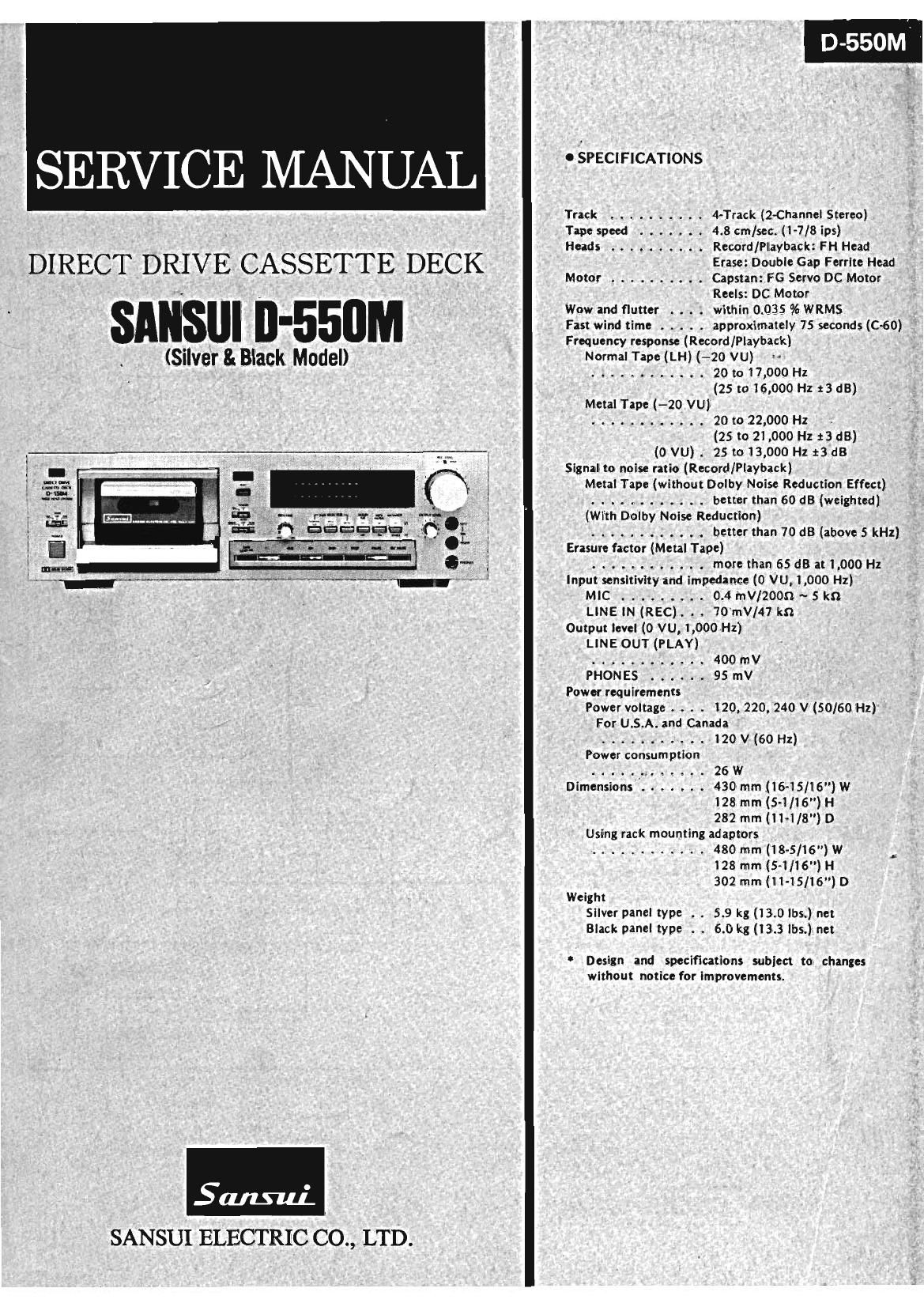
Sansui D 550 M Service Manual

This is the 15 pages manual for Sansui D 550 M Service Manual.
Read or download the pdf for free. If you want to contribute, please mail your pdfs to info@audioservicemanuals.com.

Page: 1 / 15
left right
Sansui D 550 M Service Manual

Extracted text from Sansui D 550 M Service Manual (Ocr-read)


Page 1

o SPECIFICATIONS

Track .......... 4-Track (2-Channel Stereo)
Tape speed ....... 4.8 cm/sec. (1-7/8 ips)
Heads .......... Record/Playback: FH Head
_ E:DblGFritHd
DIRECT DRIVE CASSETTE DECK Motor .......... Cazssianzo:6 eSena/«l: DZrMEtora

Reels: DC Motor

' ' Wow and flutter . . . . within 0.035 % WRMS
I Fast wind time ..... approximately 75 seconds (C760)
Frequency response (Record/Playback)

' Normal Tape (LH)(- 20 VU)
(Sllver & BlaCK Made ; ........... 20 to 17,000 Hz

(25 to 16, 000 Hz 13 dB)
Metal Tape (-20 VU)
............ 20 to 22,000 Hz .
(25 to 21,000 Hz :3 dB)
7 7777 --=-~ (0 VU) . 25 to 13,000 Hz t3dB

Signal to noise ratio (Record/Playback)
F Metal Tape (without Dolby Noise Reduction Effect)
............ better than 60 ((8 (weighted)

_r:~'_-_"1 1r - -- --~ 1 (With Dolby Noise Reduction)


: . I , "=3 3 =9??? (1 d], ............ better than 70 d8 (above 5 kHz)
3 ' 7 7 I 7 r 1". ~ ~ - -- .; I Erasure factor (Metal Tape)
' W C'- . ............ more than 65 dB at 1,000 Hz
"-M" " ' ' HM-M-r "- 1 Input sensitivity and impedance (0 VU, 1,000 Hz)
MIC ......... 0.4 "IV/2000 ~ 5 kn

LINE IN (REC). . . 70mV/47 kn
Output level (0 VU, 1,000 Hz)
LINE OUT (PLAY)

............ 400 mV
PHONES ...... 95 mV
Power requirements
Power voltage . . . . 120, 220, 240 V (50/60 Hz)
For USA. and Canada
........... 120 V (60 Hz)
Power consumption
............. 26 W
Dimensions ....... 430 mm (16-15/l 6) W

128 mm (5-1/16") H
282 mm (11-1/8") D

Using rack mounting adaptors

, ............ 480 mm (18-5/16) W
128 mm (S-l/ié") H
302 mm (1 1-15/l6") D

Weight
Silver panel type . . 5.9 kg (13.0 lbs.) net
Black panel type . . 6.0 kg (13.3 lbs.) net

Design and specifications subject to changes
without notice for improvements.

Saint-u}.
SANSUI ELECTRIC CO., LTD.

Page 2

1. BLOCK DIAGRAM

1-1. Recording Operation Block Diagram

F

MIC

LINE
IN

REC
HEAD

ERASE
HEAD

ICI DOLBY NR
MIC AMP REC LEVEL ML:
9
v '0 r** '5 [-
7 WP. _ ,Mc. p HEAD PHONE
I, [ j
C I
IZ l3 IO N l
pSIn
00st NR 01 SOURCE
_ MUTING 45)LINE GUY
IFLI REC AMP REC LEVEL ADJ l_° 5 AT R
ms PB p '° N SEASSLDEL °
A 'O
{kVR TRAP I 3 Banananu mLD
z . M T R . . . I
IBIAS ADJ VR' mOLz E E ADJ I I : : I I
- METERAMP LEVEL METER
kVRI DRIVER
R
) aIAs FINE kon m "V ' mm,
A BIAS OSC M, :
CIRCUIT
pOI~a
- ELECTRIC -°+DC
BIAS SWITCH
MA NET
COUNTER
CONTROL
LOGIC CONTROL SW'TCH
e-®- -r-]FUNCTION SWITCH

BRAKE
PLUNGER

+
CAPSTAN MOTOR
+3 n IC 2

S

REEL MOTOR PLAY PLUNGER
1-2. Playback Operation Block DIagram
I
I7
HEAD AMP MLI |__|
2 -| awr- p HEAD PHONE
I 1
IO 8 7 S 3 |
PB.LEVEL TAPE SEL 7h 0 5"
SOURCE o Dolby NR
DSIII
MUTING 0
#lOUTPuT LEVEL DUNE OUT
VR' LED PEAK INDICATOR
canal: an a
mLDI
clan: D an D
mo": METER ADJ I 5 3 E E [
METERAMP' # LEVEL METER
DRIVER

mlCI