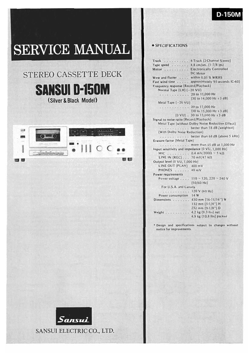
Sansui D 150M Service Manual

This is the 12 pages manual for Sansui D 150M Service Manual.
Read or download the pdf for free. If you want to contribute, please mail your pdfs to info@audioservicemanuals.com.

Page: 1 / 12
left right
Sansui D 150M Service Manual

Extracted text from Sansui D 150M Service Manual (Ocr-read)


Page 1

SERVICE MANUAL

Track .......... 4-Track (2-Channel Stereo)
Tape speed . 4.8 cmlsec. (1-7/8 ips)
Motor .......... Electronically Controlled
DC M
STEREO CASSETTE DECK Wow and flutter . . . . withirftfzfi /6 WRMS

Fast wind time .... approximately 95 seconds (C-BO)

Frequency response (Record/Playback)
SA" " - Normal Tape (LH) (-20 VU)
............ 201015900 HZ
(30 to 14,000 Hz 13 dB)
(Stlver&Black Model) Mml me How,
............ 20 to 17,000 Hz
(30 {0 .000 Hz 13 dB)
(0 VU) A 301013300 HZ :3 dB
Signal to noise ratio (Record/Playback)
Metal Tape (without Dolby Noise Reduction Effect)
............ better than 58 dB (weighted)
(With Dolby Noise Reduction)
............ better than 68 dB (above 5 kHZ)
Erasure factor (Metal Tape)
............ more than 65 dB at 1,000 Hz
Input sensitivity and impedance (0 V0, l,000 Hz)
_ MIC ......... 0.4 rnV/ZOOSZ ~ 5 kn
LINE IN (REC). . 70 mV/47 kn
- - ' 8 Output level (0 VU, 1,000 Hz)
LlNE our (PLAY) 400 mV

PHONES ...... 40 mV
Power requirements
Power voltage. , .. 110 ~120,220 ~ 240 V
(50/60 Hz)

For U.S.A. and Canada
........... 120 V (60 HZ)
Power consumption 14 W
Dimensions ....... 430 mm (16-15/16)W
132 mm (5-i/4") H
232 mm (9-1/8) D
Weight .......... 4.2 kg (9.3 lbs) net
4.9 kg (10.8 25) packed

Design and specifications subject to changes without
notice for improvements.

SANSUI ELECTRIC CO., LTD.

Page 2

1. OPERATIONS

1-1. Motion of Mechanism Section

A. Mechanism drive unit [See Fig. 1-3, Fig. 1-4 and the mecha-
nism exploded view in page 7,8)

1) When a control button is pressed, the button lever causes the
selectarm and the moving plate to move.

2) When the start lever moves, the assist gear is unlocked and starts
rotating as meshed with the flywheel gear. Then the cam of the
assist gear causes the slide plate to move.

3) The select arm of the pressed button pushes up the plate. This
plate is locked in the pushed up position by the lock plate (play/
rec lock plate @ , FF/REW lock plate @J or pause lock plate
@ ).

4) The slide plate then returns to the original position, and the
assist gear moves away from the flywheel gear and stops.

B. PLAY motion (See Fig. 1-1 and Fig. 1-3)

I) When the PLAY button is pressed, the head base is pushed up
throngh the play plate by the drive unit.

2) The pinch roller contacts the capstan shaft with pressure in this
state, and causes the tape to run at a fixed speed. The play idler
assy contacts the pulley of the tension ass'y and also the take-up
reel hub ass'y with pressure and causes the tape to be wound.

(Fig. 1-1 @)

C. REC motion (See Fig. 1-4, Top View in page 10 and mecha-
nism exploded view in page 7,8)

l) The tape running motion is same as that in PLAY motion. When

a cassette tape with anerroneous clearing preventive pawl is

mounted, recording preventive lever C7) is pushed up, and the

REC button may be pressed.

When the REC button is pressed, REC/PLAY switch (P51) in the

REC/PLAY amplifier Is switched to recording state from playing

state by the drive unit through the REC lever and flexible wire.

The mechanism is such that the PLAY button is also 0N when

the REC button is pressed.

4) A protection device is provided in order not to allow PLAY, FF
or REW human to be pressed by mistake during REC motion.

2

3

D. FF motion and REW motion (See Fig. 1-1 and Fig. 1-3)

1) When the FF button is pressed, the FF plate is pushed up by the
drive unit, causing the gear of the tension assy to be meshed
with the idler gear linked with the take-up reel hub assy. As a
result, motor revolution is transmitted to tension ass'y, idler gear
and take-up reel hub assy in this order. (Fig. 1-1 ., Fig. 1-3 .)
When the REW button is pressed, the REW plate is pushed up by
the drive unit, causing the gear of the tension ass'y to be meshed
with the gear of the supply reel hub. As a result, motor revolu-
tion is transmitted to tension ass'y and supply reel hub in this
order. (Fig. 1-1 ©, Fig. 1-3 ©)

2

Fig. 1-1 Motor Tention Belt Idler Gear Worm
Motor Pulley

Supply Reel Hub
Tention Ass'y
Faly Idler Ass'y

Capstan Belt

Auto Stop Belt WO'm

Take-up Reel Hub Ass'y

Pinch Roller Assy

E. PAUSE motion (See Fig.1-3)

I) The PAUSE motion may be made only during PLAY or REC
motion.

2) When the PAUSE button is'pressed, the PAUSE plate is pushed
up by the drive unit, causing the pinch roller to move away from
the capstan shaft and also causing through the PAUSE arm the
play idler to move away from the take-up reel hub assy. The
tape stops running as a result.

3) Simultaneously, the sensor arm and the sensor are pressed to re»
lease the auto stop, for maintaining PAUSE motion even when
the tape stops.

F. AUTO STOP motion (See Fig. 1-2)

The AUTO STOP mechanism causes all the motions (except for
PAUSE motion) to stop when the tape stops running.

1) While the tape is running, the revolution of the take-up reel hub
ass'y is transmitted to the sensor, and therefore, the sensor is
always attemping to rotate in the direction of its rotation. Con-
sequently, even when pawl CD of the auto stop cam assy ap-
proaches the sensor, the sensor moves away from this pawl.
When the running terminates, rotation of the take-up reel hub
ass'y also terminates. Therefore, the sensor loses the force to
rotate. As a result, it is pushed by pawl CD of the auto stop cam
ass'y, and pushes the stop lever and the lock plate,causing each
motion to terminate.

2

G. AMPS motion (See Fig. 1-1, Fig. 1-3 and mechanism exploded

view in page 7)

When the FF (REW) button is pressed during PLAY motion, the

FF (REW) plate is pushed up by the drive unit. At the same time,

the cue arm pushes the head base down by 1.5 mm.

The FF (REW) plate causes the gear of the tension assy to be

meshed with the idler gear (gear of supply reel hub). The FF

(REW) plate is locked in this state, allowing FF (REW) motion.

3) When a no-signal portion of the cassette tape arrives the head,
FF/REW lock plate 010 is pushed by plunger (aPSI). As a
result, FF (REW) motion only is released and PLAY motion
starts again.

2

H. TIMER PLAY/REC motion (See Fig.1-4)

The PLAY and REC button levers are equipped with button lock
mechanisms, and when the play (REC) button is pressed, the button
lever is locked. Consequently, the PLAY (REC) button is kept in
the pressed state. If the timer is set in this state, the power is on
when the set time comes, the motor starts running, the drive unit
operates and TIMER PLAY (REC) motion is performed.

Fig. 1-2

AAuto Stop Cam