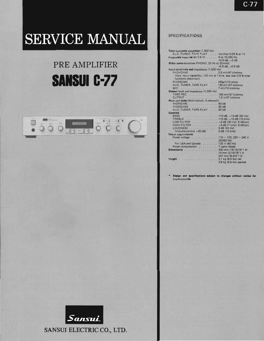
Sansui C 77 Service Manual

This is the 7 pages manual for Sansui C 77 Service Manual.
Read or download the pdf for free. If you want to contribute, please mail your pdfs to info@audioservicemanuals.com.

Page: 1 / 7
left right
Sansui C 77 Service Manual

Extracted text from Sansui C 77 Service Manual (Ocr-read)


Page 2

(3.77

1. BLOCK DIAGRAM

r
. L'Ch _ o _JEEEEEEIRBE-
mono [Iswm IrlivflaiTREBLE VR 1 NF LOOP
- HI H 10) I l
i FILTERS llswlsl | i
i } 5W Low FILTERS 1'02 I (lVRsl BASS vn FRE our
i W l . L-cn
(55ai-EIIMOMII/7Méiéaésfisd (lVRz) IJ I IJ . .
LOUDNESS (NR!) i l
TUNER SW W 4' VOLUME l AL I
e l .
L ____________ ,J
AUX I
C
I {B
l ,7" V ,_.,,I°,S,2III,,_
e , ($3511 wpm sELEcroR st ,'
.4 [05ml .5!) gvaccron I 5o ' 2%?"
. D I
Eggfecrow - 3 WIN 3 ,7 $55500?
w z [I F l u fl Ti
, (0536] J
J; iNs-ur
I SELECTOR sw L®,
5 6f i s i
(usual n 10:; 5° 0 at ,,
REC 49 WW 4 (054)
SELECTOR #773 v, I s I m so . 23-5570 K a PHONE) MM/Mc
sw ,4» . 0 3a . >-o I \ mpg-2 mono SELECTOR
t l P , i I .
Mic AMI: . sw I I I
MIClPJoi) , ~ 77777 A rrrrrrrrrrrrrrrrrrrr A
l to Ioii,iz cl PrCh
E Memr Conlrcl
icoszmsmmeur SELECTOR swi cm
olRCh
loR-Ch
2. OPERATIONS
2-1. Outlines (See Block Diagram and Fig. 2-1.) Fis 2'1 Operation of Mixing Volume (i'VR1)
- - l- ______ _1 l- ______ _l l- ______ _I
From among L-ch or R-ch SIX Independent source systems (PHONO, Igfigfgfgfinm l I I I I
TUNER, AUX, TAPE-l, TAPE-2, and MIC), two systems are select- l SignaIQpI I | | I
ed by two input selector switches (052a: front panel right side;o$3a: I : : : : :
- - Contact l
front panel left Side) The selected source signals of two systems are Pom ol | I I I I
next applied across a mixing volume (IVRl). In accordance with the WM I I I I I I . I
positions of contact points of the jVRl, the ratio of two-system I Signal®l I I I I
source signal levels (Signal A/Signal B) varies as shown in Fig. 2-], : : : : : :
Operation of Mixing Volume (iVRl )V This ratio is the output signal Igzzafifgw I I I I I
of the NR] and also becomes a prevout signal after passing through l- - - -I- - - -l I- _ _ -r- ___I I__ _ _I._ ___I
the next tone control amplifier. sfhatt POSIItIOn I I I
. . . . t 0 Mi .e el , .
On the other hand, a plastic color plate when displays sliding mixmg Inga?! V '--> Left Side Center Right Side
volume (iVRi) shaft positions and twosystem mixing conditions is VQUMEUVRU I
moved by a motor; this motor is operated by a motor control . .
circuit. V T '
Signal @e - - - ->
2-2. Motor Control Circuit (See Fig. 2-2) Mlxlng
- . . Level of
A. Operation at the time when AUTO SW (I> ) ISWS is gutpuIt
Igna
depressed liVRZI)
lf FADER AUTO SW iSWS is depressed for a moment, since a bias .
voltage Is developed between the base and emitter of iQ7, iQ7 is Sighfl'. - ---*

turned ON, By this operation, transistor, jQ§ is also turned 0N, and
thereby the motor is rotated in the normal direction (clockwise)
continuously. However, when a bias voltage is developed between
the base and emitter of I'Q7, the electrolytic capacitor iC25 is also
charged. The capacitor jC25 is next discharged and jQ7 is kept
turned ON during this discharging time, even when the switch con-
tact of iSWS is opened.

Therefore, if FADER AUTO SW is depressed for a moment, the
plastic color plate which displays the mixing state is moved con-
tinuously by the motor from the left to the right end in accordance
with the operation explained above.

1

B. Operation at the time when FADER AUTO SW ( l>)
iSWS is first depressed and FADER MANUAL SW (<1 )
jSW4 is next depressed

As explained under Paragraph A, if FADER SW ([>) jSWS is de-
pressed for a moment, the motor is kept rotated in the normal direc»
tion during a discharge time of jC25 (almost the same as a time
necessary for the plastic color plate to move from the left to the
right end), However, in order to stop the plastic color plate at any
desired position when moving, depress FADER MANUAL SW (<1)
jSW4.

Page 3

* By depressing iSW4, since bias voltages are developed between
the bases and emitters of 106 and jQ9, transistors iQG and j09
are both turned 0N. Accordingly, the electrolytic capacitor iC25
connected across [he collector and emitter of jQQ is quickly dis-
charged (under a short condition), then the base voltage of the
transistor iQ7 rises, iQ7 is turned OFF, 105 is also turned OFF,
and thus the motor stops.

C. Operation at the time when FADER MANUAL SW ( <1)
iSW4 is depressed

While the switch, jSW4 is pushed continuously, the bias voltage
between the base and emitter of 106 turns the transistor, iQ6 ON.
By this, the motor starts rotating in reverse direction (counterclock-
wise), and the plastic color plate moves from right to left end.

The circuit operation at the time when FADER MANUAL SW l iSW4 is depressed is the same as that explained under Mark * in
Paragraph B.

D.Operation at the time when FADER AUTO SW (4)
iSW6 is first depressed and next FADER MANUAL SW
( l> ) iSW3 is depressed.

Explanation on the respective operations of the iSW4 and jSWS are
omitted here, as the operation at the time when these switches are
depressed is almost the same as that of jSW4 and iSWS described
under Paragraphs A to C. However, the motor rotates in the reverse
direction (counterclockwise) and the plastic color plate moves re-
versely.

3. PARTS LOCATION & PARTS LIST

3-1. F-3289 Tone Control Circuit Board

Component Side

Ll at!
9!
an};
-l i-
(I) 93
IOHLNOO

1::g
nd

Parts List
Pam No. Slack No. Description
oJl 07219700 Mu: Jack

jVRIJ 072l0200 I00kfl1B)x 2 Volume, treble
jVRS 07210200 100KB (B) x 2 Volume, bass

3-2. F-3288 Switch Circuit Board

Parts List

Pam No. Stock No. Dmriplion
131 07209300 Selector Switch, high/low filter
054 07211200 Selector Switch, MM/MC

Fig. 2-2 Motor Control Circuit


+9V ,-.
on
c 0
R1 98
N
E E
be a
107 W
Counter 105 0 "- z;
clock E
WISE
as
'_ D
2
q
§¥
\ s
I .3
l -' 0D];
l U;
I
Clock :
C V ,
W's ' '06 03;; log 1010
i w.
i
e A
m
l e m
N
N
a T
at
9V
swllfih Indication 01 Revolving direction 01
NO Fant Pannel "19 Motor

iSW3 FADER MANUAL Counter clock Wise

jSW5 FADER AUTO //

iSW4 FADER MANUAL Clock Wise

AAVV

)SW6 FADER AUTO //

Since some of capacitors and resistors are omitted from
parts lists in this Service Manual, refer to the new Corns
mon Parts List for capacitors k resistors.

3-3. F3287 Input Mode Indicator Circuit Board
Parts List

Pans Nos Stock No. Description

0759 2800 5? LED Holder

.LED
nLD7S 03192000 SLS3ZGG
nLDaS 03192000 SLS3ZGG
nLDSS 03192000 SLSSZGG
nLDlOS 03197000 SLSBZGG
nLDllS 03192000 SLSGZGG
nLDiZS 03192000 SLSSZGG

3-4. F-3286 Input Mode Indicator Circuit Board

Parts List

Parts No. Stock No. Dlmiptian

07592800 6P LED Holder

uLED
nLDlS 03192100 SLSGZUH
nLDZS 03192100 SL532UFI
nLDSS 03192100 SLSSZUFI
nLDds 03192100 SLSSZUR
nLDSS 03192100 SLSS2UR
nLDGS 03192100 SLS32UR

o The circuit boards, F-3286, F-3287, F-3288, F3289 are not supplied as the assembled,
the individual parts on the circuit boards, however are provided for orders.