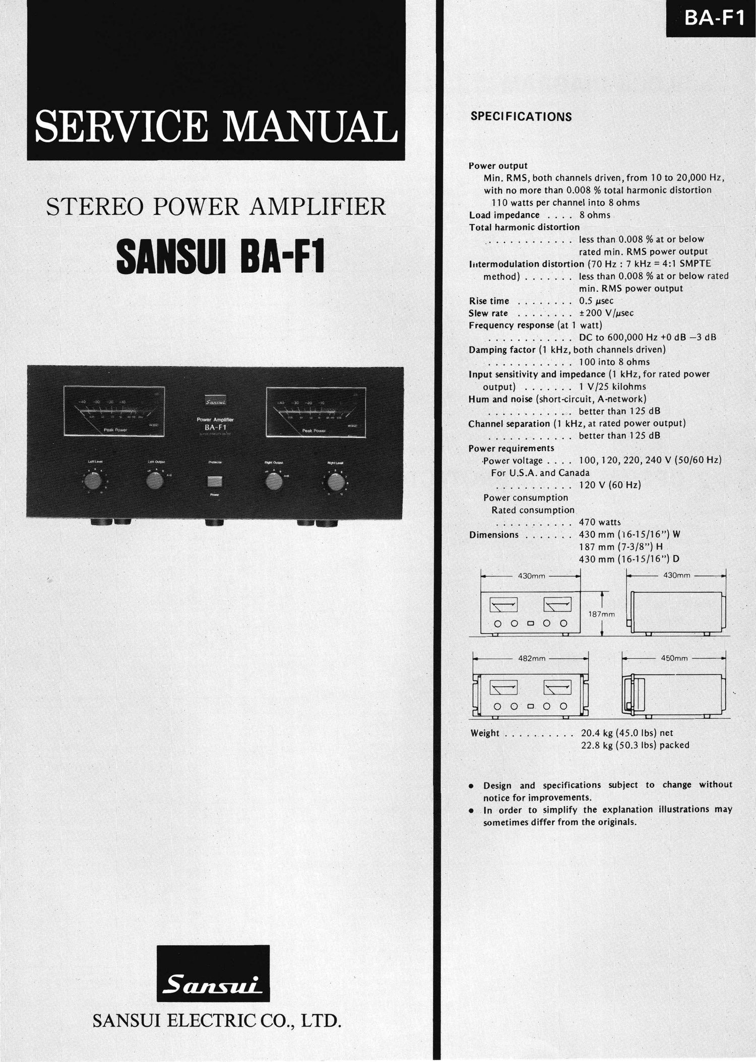
Sansui BAF 1 Service Manual

This is the 11 pages manual for Sansui BAF 1 Service Manual.
Read or download the pdf for free. If you want to contribute, please mail your pdfs to info@audioservicemanuals.com.

Page: 1 / 11
left right
Sansui BAF 1 Service Manual

Extracted text from Sansui BAF 1 Service Manual (Ocr-read)


Page 1

SERVICE MANUAL

Power output
Min. RMS, both channels driven, from 10 to 20, 000 Hz,
with no more than 0.008 _% total harmonic distortion _

STEREO POWER AMPLIFIER .....:..°.:::;::eif??:;':::.f_°*

Total harmonic distortion

. ' ' , ............ less thanfooos %'at or below
- _ ' ' rated min. RMS power outpur ,
' , , _ . ' . lntermodula-tion distortion (70 Hz : 7 kHz = 4:1 SMPTE

method) ....... less than 0.008 % at or below rated
. min. RMS power output
Rise time ........ 0.5 usec '
Slew rate . . . . . . 1200 V/psec

Frequency response (at 1 watt)
....... '. . . . . DCto600,000Hz+0dB --3dB

Damping factor (1 kHz, both channels driven)

.. ......... lOOint080hnts
Input sensitivity and impedance (l kHz, for rated power
output) ........ l V/25 kilohms

Hum and noise (short-cichit, A-network)

..... , . . . . .. better than 125 dB
Channel separation (1 kHz, at rated power output)
............ better than i 25 dB

Power requirements

. Power voltage . . . . 100, 120, 220, 240 V {50/60 Hz)
Fer U. S ..A and Canada
....... . .. l2OV(60'Hz)
Power consumption
Rated. consumption
, ..... ..... 470 watts
Dimensions ..... . 430 mm (I6 lS/i6)W
' 187 mm (7- 3/8) H.
' 430 mm (l6-lS/l6) D

Paws! Amplifier

-3?

-4- 430mm ¥---'-o- 430mm
~\-~ «T... I
, i87mm
O O D O O l
U LI U >L-L

k- 482mm 450mm
0 o- c: o o .
Weight . . .. ..... 20.4 kg (45.0 lbs) net

22.8 kg (50.3 lbs) packed

0 Design and specifications subject to change without

notice for improvements
0 .In order to simplify the explanation illustrations may

. sometimes differ from the originals

SANSUIELECTRIC co, LTD.

Page 2

1. BLOCK DIAGRAM

f n
Pre-DrIver
Diamond DifferentIal CIrCUIt(DD/DC)
r ------------------- 1
I l
+63V f E g 0.; f I Lina
: . ~ 1
I TRoz J TRos '
' " TRIO :
i 4 pk m +56v
_ I
F. I I- I a d- m mm T PL705
'L I ~ + I I IndIcatIng
T I TR04 TRos I TR70I Overload DetectIon CIrCUIt
h J i I | ~____
7- FETOI I : 43 ' 6C DrIft DetectIon (I
AC cr-J I I 5 . v I '0 h I
VROI I I 0 I TR TRIS TWO? I ' T
It '~ TR07 f ' 1 Protector PI Peak Meter
,I, I TROS I i I CIrCUIt +8 fl Amp.
TROI ; r I I It -56V
I TRII I _
i TRoe I II. ~ i am
. I I
' I, '.
-63V I l i i "lb I
L ___________________ J
L J
2. OPERATION OF PROTECTOR CIRCUIT
Fig. 2-2 Schematic Diagram of HA-12002
In the protector circuit of BA-FI, lC/HA-12002 is adopted to pre- Ir __________________ "|
vent G) the damage on speakers caused by the DC-drift Q) the I 3 2 I I
overcurrent flowing the output stage due to the overload and C3) : H3 :6 kg :
the pop-noise occurred at switching the power. I § :
The configuration of the protector circuit and the interior schematic : o D I
diagram of HA-l2002 are shown in Figs. 2-1 and 2-2, respectively. I o 8 I, I R-ch QC Drift
I fl] Detection
Fig. 2-1 Configuration of protector Circuit : g I
L-ch Output Stage I 8' o I
I
TR70I I 2 m :3 A _
I r 8 m 9.. L-Ch DC Drift
l V Detection
l I
I
R70I Relay I '
7 P96? Speaker(L) I G) Overload Detection
I
+ w. +8 I :
HAI2002 §R09 - C603 : I
TR703 ' R604 ' -
.n + I DC BIas(-)
0% _ C604 I
I
L-Ch , / I
From .
Overload I
Overload Detector +
098 R-ch(TR02. R702) *CO' I
+ m- '
Power Transformer _ _ C02 : DC Bias(+)
+ + 48V I Delaying Circuit
§Rlo [.034 :
_ h ; I
R c Output Stage wfi Speaker(R) I
I
I
I
I
I
l
l
I
l

Speaker Relay

8+