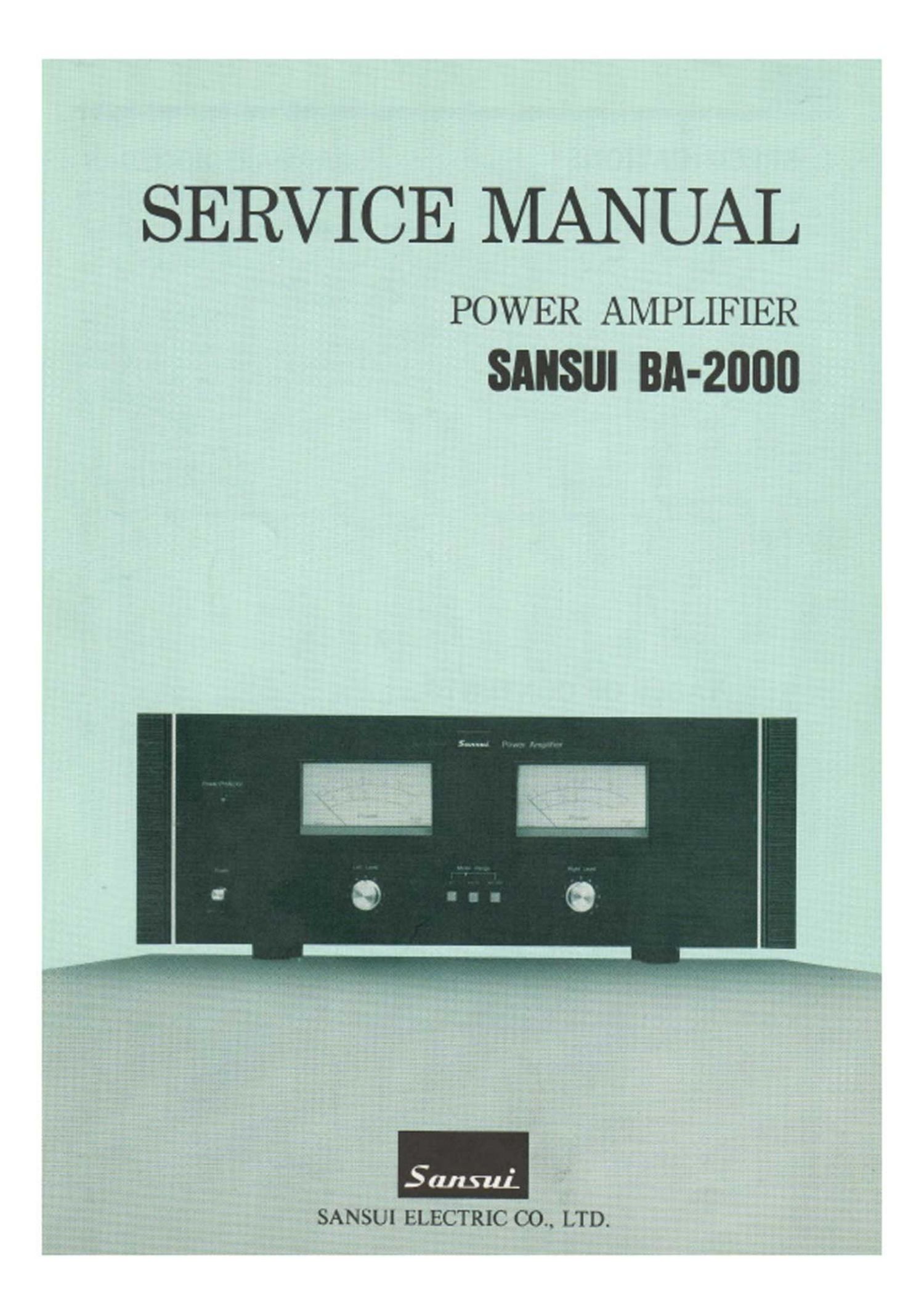
Sansui BA 2000 Service Manual

This is the 13 pages manual for Sansui BA 2000 Service Manual.
Read or download the pdf for free. If you want to contribute, please mail your pdfs to info@audioservicemanuals.com.

Page: 1 / 13
left right
Sansui BA 2000 Service Manual

Extracted text from Sansui BA 2000 Service Manual (Ocr-read)


Page 2

1. SPECIFICATIONS

POWER OUTPUT
Min. RMS, both channels driven, from 10 to 20,000Hz,
with no more than 0.03% total harmonic distortion.

110 watts per channel into 8 ohms

Min. RMS, both channels driven, at 1,000Hz, with no more
than 0.03% total harmonlc dlstortion In stereo operation.
115 watts per channel into 8 ohms

LOAD IMPEDANCE ........ 8 ohms

POWER BANDWIDTH ...... 10 to 20,000Hz at or below
rated min. RMS power
output and total harmonic
distortion

TOTAL HARMONIC DISTORTION

.................... less than 00.3% at or below
rated min. RMS power
output

INTERMODULATION DISTORTION

(70Hz : 7,000Hz=4: 1 SMPTE method)
.................... less than 0.03%
FREQUENCY RESPONSE (at 1 watt)
.................... 5H2 to 100kHz :?dB

DAMPING FACTOR ........ approximately 70 at 8 ohms
load
CHANNEL SEPARATION (at rated output, 1kHz)
.................... better than 75dB

HUM AND NOISE (IHF) . . . .better than 115dB

INPUT SENSITIVITY AND IMPEDANCE
(1kHz, for rated power output)

.................... 1,000mv 50m
GENERAL
POWER VOLTAGE ........ 100, 120, 220, 240v 50/60Hz
(U.S.A & Canada) ...... 120V (Usable 110-130V)60Hz

POWER CONSUMPTION . .910 watts (max)
480 watts 595VA (rated)
DIMENSIONS .............. 460 mm (18-1/8) W
160 mm (6-5/16) H
375 mm (14-13/16) D
WEIGHT .................. 18.3 kg (40.3 lbs) net
20.8 kg (45.0 lbs) packed

Design and Specifications subject to change without notice for
improvements.

TABLE OF CONTENTS

Secsion Title Page
1. SPECIFICATIONS .................................................. 1
2. BLOCK DIAGRAM .................................................. 2
3. OPERATING DIAGRAM ............................................ 2
4. OPERATION OF NEW CIRCUIT .................................... 3

4-1. Current Mirror Circuit .......................................... 3

5. ADJUSTMENTS .................................................... 4

5-1. Bias Current Adjustment ........................................ 4

5-2. Power Meter Adjustment ........................................ 4

6. PARTS LISTS 8s PARTS LOCATION ................................ 5

6-1. F-2661 Driver Circuit Board ...................................... 5

6-2. F-2630'Power Supply Circuit Board for Driver Stage ................ 6
6-3. F-2629 Power Supply Circuit Board .............................. 7

6-4. F-2631 Level Volume & Meter Circuit Board ...................... 7

6-5. F-2514 Meter Lamp Circuit Board ................................ 8

6-6. F-2581 Final Stage Circuit Board .................................. 8

6-7. F-2506 Input Terminal Circuit Board .............................. 8

7. OTHER PARTS .................................................... 9

7-1. Top 8: Bottom View ............................................ 9

7-2. Front View .................................................... 10

7-3. Figures ........................................................ 10

8. SCHEMATIC DIAGRAM .......................................... 11

9. PACKING LIST ............................................ BACK covm

10. ACCESSORY PARTS LIST ................................ BACK coves