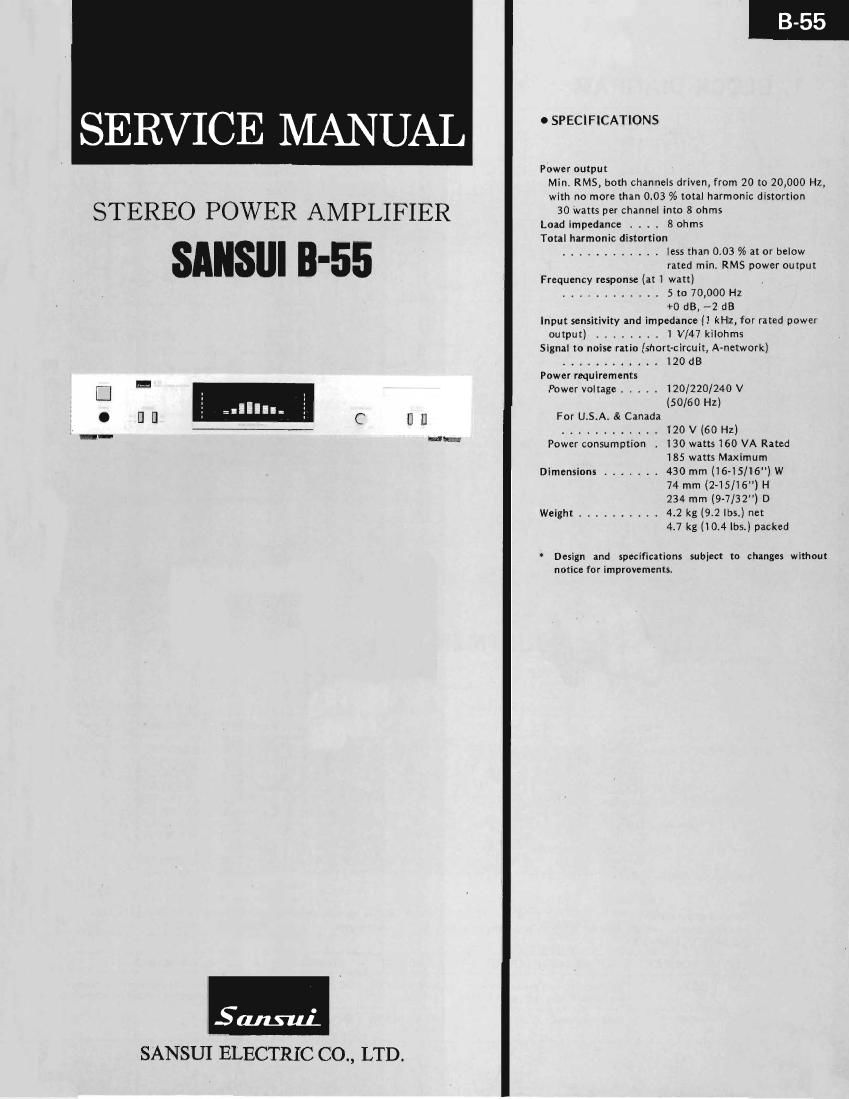
Sansui B 55 Service Manual

This is the 9 pages manual for Sansui B 55 Service Manual.
Read or download the pdf for free. If you want to contribute, please mail your pdfs to info@audioservicemanuals.com.

Page: 1 / 9
left right
Sansui B 55 Service Manual

Extracted text from Sansui B 55 Service Manual (Ocr-read)


Page 1

SERVICE MANUAL

Power output
Min. RMS, both channeis driven, from 20 to 20,000 Hz.
with no more than 0.03 % total harmonic distortion
STEREO POWER AMPLIFIER 30 watts per channel into 8 ohms
Load impedance . . . . 8 ohms
Total harmonic distortion
............ less than 0.03 % at or below
- rated min. RMS power output
Frequency response (at 1 watt) _
............ 5 to 70,000 Hz
+0 dB, ~2 dB
Input sensitivity and impedance (1 kHz, for rated power
output) ........ 1 V/47 kilohms
Signal to noise ratio (short-circuit, A~network)
............ IZO dB
Power requirements
a" Power voltage ..... 120/220/240 v
[1 [I C n H For U.S.Ai & Canada
--h- ............ 120 V (60 Hz)
an Power consumption , 130 watts 160 VA Rated
185 watts Maximum
Dimensions ....... 430 mm (16.15/16")w
74 mm (2-15/16") H
234 mm (9-7/32") D
Weight .......... 4.2 kg (92 lbs.) net
4.7 kg (104 lbs.) packed

ioi:

* Design and specifications subject to changes without
notice for improvements

SANSUI ELECTRIC CO., LTD.

Page 2

1. BLOCK DIAGRAM

inpul
+3
3: 1

Fm. Amp

macaw Drm Amp

3

No 5m. n9
Swascv .

5mm".
Analyzer

Speclrum Analyzer + 8
Duncan: Drwe ercvil

M01

a
9
c

%

\/\

w
@ W1
. w
Speclrum Annilzer

Display Um!
3

/®\

ur

niCAd {I [C .1
Counter
m c '
:qu
700*" ma non)
* B

' Since we Non Switching Bias Circuit empkwad in B55 is similar to mm of AU-D7 and the Specrrum Analizer
Circuit employed in 3-55 is similar (0 mar of B»77, the explanaflon 0 there urcuit is omitted from this manual,
thereiore pleaxe relzr m the page 1, 2, Dn iervice manual of AU-D7 and page 2, on service manual of 3-77.

2- BIAS CURRENT ADJUSTM ENT (Refer to figure below)

Note:

14 Room Temperature

2, For adjustment, run the unit for more than 3 minutes after

DC Volr Meter

3 Bottom Side

DC Volt Meter

5

? 9" '? Y
K K
Q10 Q9 09 010
E E E E
(fl-CH) O O
' kVR'I-R kVRirL
........ 18°C ~ 38°C 3. Before turning ON power switch, turn kVRI on F-3536 fully

the power is switched on.

cou nterwise.

STEP SUBJECT MEASURE OUTPUT ADJUST ADJUST FOR REMARKS
1. L-CH Connect DC volt meter between kVRI (L-CH) DC 3 mV This bias current adjustment converts
emitters of ng, ka on F-3536 F-3536 current value into voltage by ohms law
2. R-CH Same as above kVR1 (R-CH) DC 3 mV
F3536

Page 3

3. OTHER PARTS

3-1. Front View

9 Output Terminal 9 Input Terminal

mTl

PS1
nPL2
PF1
Parts List (Front View) Parts List
Pam No. Stock No. Description Part: No. Stock No. Description
1 07769600 Front Panel Assy nVR1 46118400 Variable Resistor 100k (B),
1-1 07770000 Front Panel analyzer level
172 53195000 Knob, power
1-3 59560800 Knob Guide, power pFl 07188800 AC Fuse 3A (120V)
1-4 07763700 Front Glass 07188500 AC Fuse 1 ,5A (220V)
1-5 07768900 Badge Assy
1-6 07553900 Push Knob Assy mT1 15003801 Power Transformer
1-7 07768600 Dress Sash

ps1 46087300 Power Switch
07768500 Peek POWBI & Analyzer Scale
07769300 Bonnet nPL1 07237800 FGMSAS, Spectrum Analyzer
07763600 Side Panel, Right
07776200 Knob, Analyzer
46078100 Head Phone Jack
07763500 Side Panel, left

38004700 Power Cord
39106000 Strain Relief
07189600 AC Outlet

07192000 Hexagon Space Screw
07769800 Badge Lighting Frame

#0301me

U11>mN-