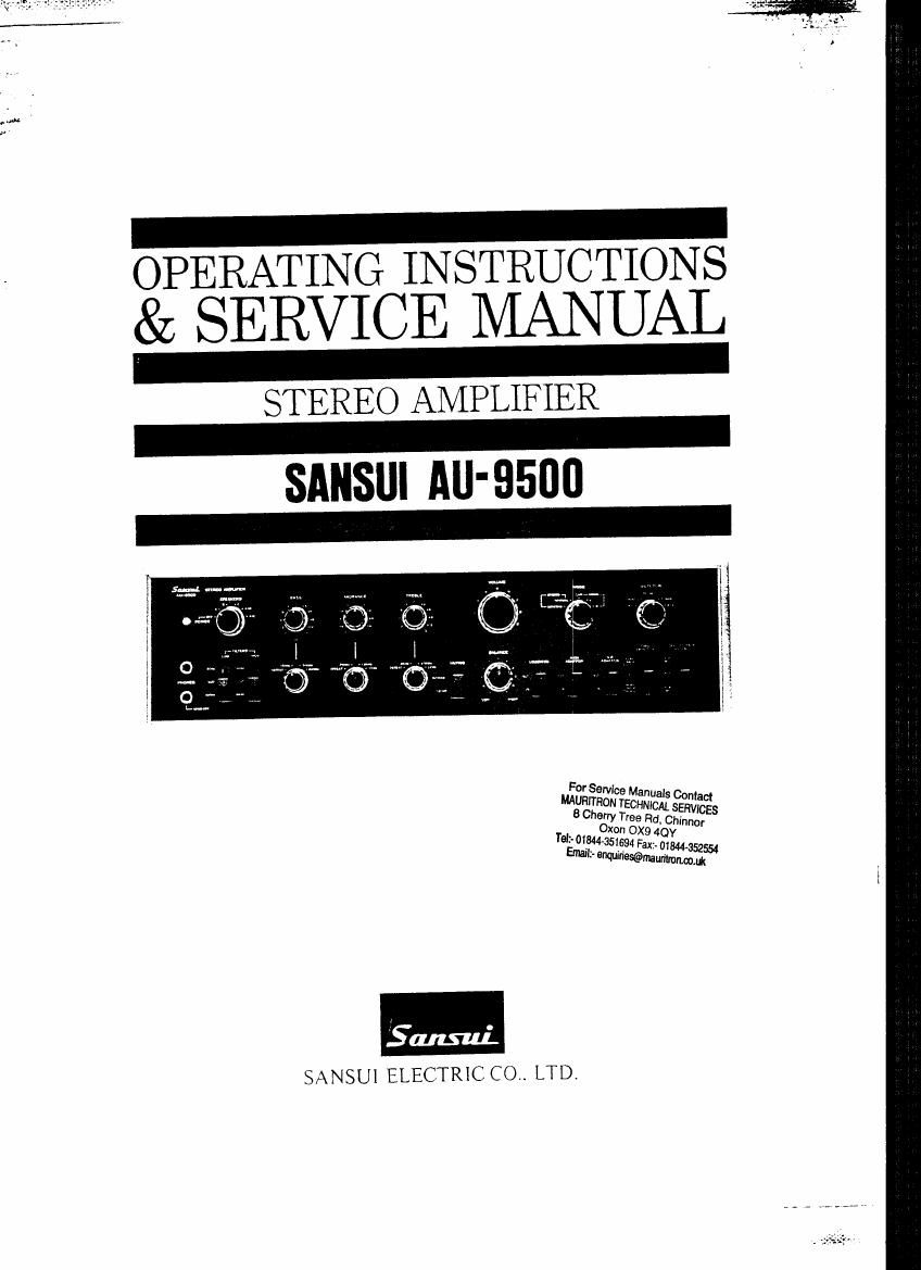
Sansui AU 9500 Owners Manual

This is the 34 pages manual for Sansui AU 9500 Owners Manual.
Read or download the pdf for free. If you want to contribute, please mail your pdfs to info@audioservicemanuals.com.

Page: 1 / 34
left right
Sansui AU 9500 Owners Manual

Extracted text from Sansui AU 9500 Owners Manual (Ocr-read)


Page 1

TING INSTRUCTIONS
ggRfiRVICE MANUAL

STEREO AMPLIFIER

SANSUI AU'9500

For Service Manuals Contact
MAURITRON TECHNICAL SERVICES
8 Cherry Tree Rd, Chinnor
Oxon OX9 4QY
Tali-01344651694 Fax:- 01544352554

Email:- mmfiwmmmwm

SANSUI ELECTRIC CO. LTD.

Page 2

We are grateful for your choice of the AU-9500 Integrated
Amplifier.

* For over a quarter of a century,~Sansui has been building hi-fi audio
equipment, and nothing else. Our mission is very old and at once
ever new to us: to bring the reproduced sound closer and closer to
the original.

The AU-9500 now in your hands is one answer from us to this
never-ending quest. It is a product of the cream of highly advanced
modern audio-electronics knowhow, coupled with our long experi-
ence. As such, we present it to you with our full confidence.

The AU~9500 incorporates an all«stage direct-coupled pure com-
plementary power amplifier that delivers a continuous power output
of 85 watts per channel (each channel driven) into 8 ohms, with the
total harmonic distortion of less than 0.1% over the entire audio
spectrum. It connects three pairs of speaker systems, two turntables
and two tape decks, while offering such sophisticated refinements
as triple tone controls with adjustable turnvover/roll-off frequencies,
inputs for a 4-channel adaptor and a noise reduction adaptor,
preamplifier outputs and power amplifier inputs, tape-to-tape
reprint facilities, and an audio muting switch.

This manual has been prepared to guide you in operating and caring
for the amplifier correctly, so that you will obtain the most out of
its built-in high performance and exceptional versatility.

May we suggest that you read it once carefully?

CONTENTS


SWITCHES AND CONTROLS ................................. 3, 4, 5, 6
CONNECTING SPEAKER SYSTEMS/

PLAYING RECORDS ................................................ 7, 8
RADIO RECEPTION/USING MICROPHONES .................. 9
QUICK CHECK LIST OF SIMPLE MISTAKES .................. 10
RECORDING AND PLAYBACK BY TAPE DECKS ......... ll, 12
UPGRADING YOUR STEREO (4-CHANNEL STEREO

SYSTEM/ELECTRONIC CROSSOVER SYSTEM) ............ 13
SIMPLE MAINTENANCE HINTS .............................. 14, 15
SPECIFICATIONS ................................................... 16
SCHEMATIC DIAGRAM .......................................... 17, 18
GENERAL TROUBLESHOOTING CHART ..................... 19
DISASSEMBLY PROCEDURE .................................... 2O
ALIGNMENT .................................................. .i
PRINTED CIRCUIT BOARDS AND PARTS LIST ......... 23~ 32

OTHER PARTS AND THEIR POSITION ON CHASSIS ...33, 34

Page 6

CONNECTING SPEAKER SYSTEMS/ PLAYING RECORDS

Connecting Speaker Systems

If you are connecting only one pair of speaker
systems to the AU-9500, they may have any imped-
ance from 4 to 16 ohms. Connect them,to the SYS-
TEM A, B or C terminals on the rear panel, making
sure not to confuse the left and right cables, plus
and minus leads on the amplifier and speaker ends.
But if you wish to connect two pairs of speaker
systems and drive them simultaneously by turning
the Power/Speakers Switch to A+B or A+C, each
speaker system should have an impedance of 8 to 16
ohms. Using a system with a lower impedance could
result in a breakdown of the amplifier.

Phasing of Speakers

First listen to the monophonic reproduction of any
program source. If the speaker systems are in phase,
the sound will seem to come from a point midway
between the left and right speaker systems. If the
sound is not directly in front of you, however, the
speaker systems are out of phase. If you notice
this condition, check the speaker connections once.
To correct the condition, switch the amplifier off and
reverse the connection of plus and minus leadwires
of one speaker cable.

Connecting a Turntable

Connect it to the PHONO l or 2 terminals on the
rear. For best results, use a turntable with a mag
netic pickup cartridge.

if you use a turntable with a crystal or ceramic
cartridge, connect it to the AUX terminals.

Phone-2 Pickup Load Switch

The input impedance of the PHONO~2 circuit can
be switched over from 30k!) to 50k!) to 100k!)
with the PHONO-Z Pickup Load Switch on the
rear panel. Its purpose is to match the load re-
sistance of the cartridge in use, since different
cartridges have different load resistance values and
the magnitude of the impedance of a phono input
circuit affects the level of high-frequency sound
among other things.

Most cartridges have a load resistance value of
5011!), which is why the input impedance of the
PHONO-l circuit is also 50km. If you have con-
nected your turntable to the PHONO-Z circuit and
find little difference in the reproduced tone quality
as you change over the PHONOQ Pickup Load
Switch. leave the switch at the 60k!) position.

Playing Records

1. Set the Selector Control to PHONO-l or
PHONO-Z, depending on which input circuit you
are using.

2. Set the Power/Speakers Switch to as required.
3. Switch on the turntable, adjusting it for the right
speed of the record to be played,

4. Start playing the record.

5. Use the amplifiers other controls and switches
to suit your taste or room acoustics.

For Service Manuals Contact
MAURITRON TECHNICAL SERVICES
8 Cherry Tree Rd, Chinnor
Oxon 0X9 4QY
Tdt- 01844451694 Fax:- 01844-35253
Emilr mwmmmmm